
Related Manuals for Toro 31914


Summary of Contents for Toro 31914
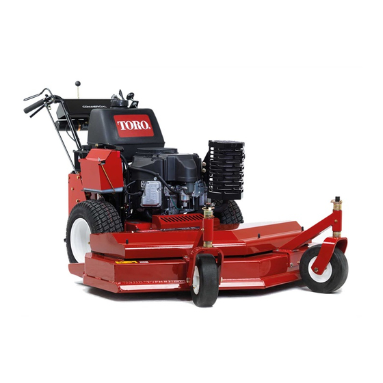
- Page 1 Form No. 3450-388 Rev A Commercial Walk-Behind Traction Unit 18HP Pistol-Grip Hydro Drive Model No. 31914—Serial No. 410300000 and Up *3450-388* Register at www.Toro.com. Original Instructions (EN)
-
Page 2: Table Of Contents
Whenever you need service, genuine Toro parts, or additional information, contact an Authorized Service Dealer or Toro Customer Service and have the model and serial numbers of your product ready. Figure 1 sa-black... -
Page 3: Safety
Safety Operating the Neutral Locks ......13 Operating the Blade-Control Switch (PTO) ............14 This machine has been designed in accordance with Driving the Machine .......... 14 EN ISO 5395. Bringing the Machine to Neutral ......15 Adjusting the Height of Cut ....... 15 After Operation ............ -
Page 4: Safety And Instructional Decals
Safety and Instructional Decals Safety decals and instructions are easily visible to the operator and are located near any area of potential danger. Keep safety signs clear and visible, replace any decal that is damaged or missing. decal95-5852 95-5852 1. Warning—engage the parking brake and block the wheels decalbatterysymbols Battery Symbols when parking on a slope. - Page 5 decal115-4212 115-4212 1. Hydraulic oil level 3. Warning—do not touch the hot surface. decal130-8370 130-8370 2. Read the Operator's Manual. 1. Neutral lock decal130-8375 130-8375 1. Read the Operator's 4. Increase right Manual. 5. Tracking adjustment knob 2. Increase left 3.
-
Page 6: Setup
Setup Loose Parts Use the chart below to verify that all parts have been shipped. Procedure Description Qty. – No parts required Check the fluids and tire pressure. Wheel Kit (sold separately) Install the Wheel Kit. Mower deck (sold separately) Install the mower deck. -
Page 7: Product Overview
Controls Product Overview Become familiar with all the controls (Figure 4) before you start the engine and operate the machine. Control Panel g016076 Figure 3 1. Mower deck (sold 4. Controls separately) 2. Parking brake 5. Handle 3. Fuel tank 6. -
Page 8: Specifications
This machine has a variable speed control with a To ensure optimum performance and continued safety position. This controls how fast the machine EUTRAL certification of the machine, use only genuine Toro travels. replacement parts and accessories. Replacement parts and accessories made by other manufacturers... -
Page 9: Before Operation
Operation • Do not fill containers inside a vehicle or on a truck or trailer bed with a plastic liner. Always place containers on the ground, away from the vehicle Before Operation before filling. • Remove equipment from the truck or trailer and refuel it on the ground. -
Page 10: Using The Safety-Interlock System
Filling the Fuel Tank Engage the neutral locks and move the speed-control lever to the N position. EUTRAL Park the machine on a level surface. Start the engine. Engage the parking brake. Without holding the operator-presence control Shut off the engine and remove the key. (OPC) levers, engage the blade-control switch Clean around the fuel-tank cap. - Page 11 Do not operate a machine under any conditions – Use only accessories and attachments where traction, steering or stability is in question. approved by The Toro® Company. Be aware that operating the machine on wet – Be sure of your footing while using this grass, across slopes or downhill may cause the machine, especially when backing up.
-
Page 12: Operating The Parking Brake
Starting the Engine braking and steering. The machine can slide even if the drive wheels are stopped. Connect the wires to the spark plugs. • Remove or mark obstacles such as ditches, holes, Open the fuel valve. ruts, bumps, rocks, or other hidden hazards. Tall grass can hide obstacles. -
Page 13: Operating The Neutral Locks
g001508 Figure 8 1. Handle 4. Drive lever 2. Neutral lock 5. Full speed forward 3. N position 6. R position EUTRAL EVERSE g027797 Disengaging the Neutral Locks Figure 7 1. Throttle lever 3. Choke Squeeze the drive levers rearward until you feel 2. -
Page 14: Operating The Blade-Control Switch (Pto)
Operating the Driving the Machine Blade-Control Switch The throttle control regulates the engine speed (rpm). Move the throttle control to the F position for the (PTO) best mowing performance. The blade-control switch (PTO), used in conjunction Driving Forward with the operator-presence control, engages and disengages power to the mower blades. -
Page 15: Bringing The Machine To Neutral
Bringing the Machine to Open the bypass valves by turning them counterclockwise 1 to 2 turns (Figure 12). Neutral Note: This allows hydraulic fluid to bypass the pumps and the wheels to turn. Always engage the neutral lock and parking brake when you stop the machine. -
Page 16: Maintenance
Carefully release pressure from components with stored energy. • To ensure safe, optimal performance of the machine, use only genuine Toro replacement parts. Replacement parts made by other manufacturers could be dangerous, and such use could void the product warranty. -
Page 17: Recommended Maintenance Schedule(S)
• Replace the fuel filter. • Change the hydraulic filter and hydraulic fluid when using Mobil® 1 fluid. Every 250 hours • Change the hydraulic filter and the hydraulic fluid when using Toro® HYPR-OIL™ Every 500 hours 500 hydraulic fluid. -
Page 18: Lubrication
Lubrication Engine Maintenance Greasing the Machine Engine Safety • Do not change the governor speed or overspeed Grease the machine more often in dirty or dusty the engine. conditions. • Run the engine dry or remove the fuel with a hand Grease Type: No. -
Page 19: Servicing The Engine Oil
Servicing the Engine Oil Note: Change the oil more frequently when the operating conditions are extremely dusty or sandy. Engine-Oil Specifications Engine-Oil Type: Detergent oil (API service SF, SG, SH, SJ, or SL) Crankcase Capacity: 1.7 L (58 oz) with the filter removed;... - Page 20 Changing the Engine Oil Service Interval: After the first 8 hours—Change the engine oil. Every 100 hours—Change the engine oil (more often in dirty or dusty conditions). Park the machine so that the drain side is slightly lower than the opposite side to ensure that the oil drains completely.
- Page 21 Changing the Engine-Oil Filter Service Interval: Every 200 hours—Change the engine-oil filter (more often in dirty or dusty conditions). Drain the oil from the engine; refer to Changing the Engine Oil (page 20). Change the engine-oil filter (Figure 19). g194610 Figure 18 Dispose of the used oil at a recycling center.
-
Page 22: Servicing The Spark Plug
Servicing the Spark Plug Checking the Spark Plug Important: Do not clean the spark plug(s). Service Interval: Every 100 hours Always replace the spark plug(s) when it has a Ensure that the air gap between the center and side black coating, worn electrodes, an oily film, or electrodes is correct before installing the spark plug. -
Page 23: Fuel System Maintenance
Replacing the Fuel Filter Fuel System Maintenance Service Interval: Every 200 hours/Yearly (whichever comes first) Important: Never install a dirty filter if it is DANGER removed from the fuel line. In certain conditions, fuel is extremely Park the machine on a level surface, disengage flammable and highly explosive. -
Page 24: Electrical System Maintenance
Electrical System Maintenance Electrical System Safety • Disconnect the battery before repairing the machine. Disconnect the negative terminal first and the positive last. Connect the positive terminal first and the negative last. • Charge the battery in an open, well-ventilated area, away from sparks and flames. - Page 25 Charging the Battery Installing the Battery Install the battery as shown in Figure WARNING Charging the battery produces gasses that can explode. Never smoke near the battery and keep sparks and flames away from battery. Important: Always keep the battery fully charged (1.265 specific gravity) to prevent battery damage when the temperature is below 0°C (32°F).
-
Page 26: Servicing The Fuses
Servicing the Fuses Drive System Maintenance The electrical system is protected by fuses. It requires no maintenance. If a fuse blows, check the component or circuit for a malfunction or short. Perform the following linkage adjustments, Adjusting the Speed-Control Linkage (page 26) through Park the machine on a level surface, disengage Adjusting the Tracking (page... - Page 27 g267691 Figure 29 g001517 Figure 30 1. Yoke 6. Tabs—3 o’clock position 2. Jam nut 7. Tabs—6 o’clock position 1. Actuating tab 3. Safety switch 3. Speed-control crank 8. Tabs—9 o’clock position 2. 8 mm (5/16 inch) space 4. Speed-control rod 9.
-
Page 28: Adjusting The Neutral-Control Linkages
Adjusting the Squeeze 1 drive lever until you feel an increase in resistance. Neutral-Control Linkages This is where neutral should be. Note: Ensure that you have not reached the WARNING end of the neutral-lock slot. If you have, shorten the control-lever linkage; refer to Adjusting the The engine must be running when you Control Rod (page... -
Page 29: Adjusting The Hydraulic Control Linkages
Adjusting the Hydraulic Loosen the front adjusting nut on left hydraulic control linkage (Figure 33). Control Linkages Turn the left, rear adjusting nut counterclockwise until the wheel rotates forward (Figure 33). WARNING Turn the rear adjusting nut clockwise 1/4 of a turn at a time. - Page 30 Adjusting the Right Linkage Move the speed-control lever to the N EUTRAL position. Move the right drive lever to the full F ORWARD position. Adjust the right linkage by turning the quick track knob counterclockwise until the tire begins to rotate forward (Figure 35).
-
Page 31: Adjusting The Control Rod
Adjusting the Control Rod Release and engage the neutral lock, and ensure that the tire does not rotate (Figure 37). Continue this process until the tire does not Checking the Control Rod rotate. With the rear of the machine still on jack stands Install the hairpin cotter between the drive levers and the engine running at full throttle, move and neutral locks and into the clevis pins... -
Page 32: Adjusting The Tracking
Adjusting the Tracking If the machine does not track straight, adjustment is required. Remove the machine from the jack stands. Check the rear tire pressure; refer to Checking the Tire Pressure (page 32). Run the machine and observe the tracking on a level, smooth, hard surface, such as concrete or asphalt. -
Page 33: Cooling System Maintenance
Brake Maintenance Cooling System Maintenance Servicing the Parking Brake Cleaning the Air-Intake Checking the Parking Brake Screen Service Interval: Before each use or daily Check the brakes on both a level surface and a slope. Remove any buildup of grass, dirt, or other debris from the cylinder and cylinder head cooling fins, Park the machine on a level surface and the air-intake screen on the flywheel end, and the... -
Page 34: Belt Maintenance
Belt Maintenance Note: With the parking brake in the disengaged position, the clearance between the tire and the flat bar is approximately 6 mm (1/4 inch). Inspecting the Belts Secure the lower link to the lower brake lever using the hairpin cotter and the clevis pin (Figure Service Interval: Every 25 hours—Check the belts 41). -
Page 35: Hydraulic System Maintenance
You can check the oil when the fluid is warm or Every 500 hours—Change the hydraulic filter cold. The baffle inside the tank has 2 levels depending and the hydraulic fluid when using Toro® on the temperature. HYPR-OIL™ 500 hydraulic fluid. -
Page 36: Bleeding The Hydraulic System
Bleeding the Hydraulic and a rubber band to prevent all of the hydraulic fluid from draining out. System Locate the hydraulic filter under the engine base and place a drain pan under the filter (Figure 43). The traction system is self-bleeding; however, it may be necessary to bleed the system if you change the fluid or after work is performed on the system. -
Page 37: Checking The Hydraulic Hoses
Cleaning Cleaning under the Mower Service Interval: Before each use or daily Remove the grass buildup under the mower daily. Park the machine on a level surface, disengage the PTO, and engage the parking brake. Shut off the engine, remove the key, and disconnect the spark-plug wires from the spark g001515 Figure 44... -
Page 38: Storage
Storage Add fuel stabilizer/conditioner to fresh fuel in the tank. Follow mixing instructions from the fuel stabilizer manufacturer. Do not Storage Safety use an alcohol-based stabilizer (ethanol or methanol). • Always shut off the machine, remove the ignition Run the engine to distribute conditioned fuel key, wait for all moving parts to stop, and allow through the fuel system for 5 minutes. -
Page 39: Troubleshooting
Troubleshooting Problem Possible Cause Corrective Action The engine does not start, starts hard, or 1. The fuel tank is empty. 1. Fill the fuel tank with fuel. fails to keep running. 2. The fuel-shutoff valve is closed. 2. Open the fuel-shutoff valve. 3. - Page 40 Problem Possible Cause Corrective Action The blades do not rotate. 1. The mower deck belt is worn or loose. 1. Check the belt tension. 2. The mower deck belt is broken. 2. Install a new deck belt. 3. The mower deck belt is off a pulley. 3.
-
Page 41: Schematics
Schematics g016112 Electrical Schematic (Rev. A) g001544 Hydraulic Schematic (Rev. A) - Page 42 Notes:...
- Page 43 The Toro Company (“Toro”) respects your privacy. When you purchase our products, we may collect certain personal information about you, either directly from you or through your local Toro company or dealer. Toro uses this information to fulfil contractual obligations - such as to register your warranty, process your warranty claim or to contact you in the event of a product recall - and for legitimate business purposes - such as to gauge customer satisfaction, improve our products or provide you with product information which may be of interest.
Need help?
Do you have a question about the 31914 and is the answer not in the manual?
Questions and answers