Table of Contents
Advertisement
Quick Links
Screw liquid chillers are designed to provide safe and re-
liable service when operated within design specifica-
tions. When operating this equipment, use good judgment
and follow safety precautions to avoid damage to equip-
ment and property or injury to personnel.
Be sure you understand and follow the procedures and
safety precautions contained in the machine instruc-
tions as well as those listed in this guide.
DO NOT VENT refrigerant relief devices within a building. Outlet
from rupture disc or relief valve must be vented outdoors in ac-
cordance with the latest edition of ANSI/ASHRAE 15 (American
National Standards Institute/American Society of Heating,
Refrigeration, and Air Conditioning Engineers). The accumulation
of refrigerant in an enclosed space can displace oxygen and cause
asphyxiation.
PROVIDE adequate ventilation in accordance with ANSI/ASHRAE
15, especially for enclosed and low overhead spaces. Inhalation of
high concentrations of vapor is harmful and may cause heart ir-
regularities, unconsciousness, or death. Intentional misuse can be
fatal. Vapor is heavier than air and reduces the amount of oxygen
available for breathing. Product causes eye and skin irritation. De-
composition products are hazardous.
DO NOT USE OXYGEN to purge lines or to pressurize a machine
for any purpose. Oxygen gas reacts violently with oil, grease, and
other common substances.
DO NOT USE air to leak test. Use only refrigerant or dry
nitrogen.
NEVER EXCEED specified test pressures. VERIFY the allowable
test pressure by checking the instruction literature and the
design pressures on the equipment nameplate.
DO NOT VALVE OFF any safety device.
BE SURE that all pressure relief devices are properly installed and
functioning before operating any machine.
DO NOT WELD OR FLAMECUT any refrigerant line or vessel
until all refrigerant (liquid and vapor) has been removed from chiller.
Traces of vapor should be displaced with dry air or nitrogen and
the work area should be well ventilated. Refrigerant in contact with
an open flame produces toxic gases.
DO NOT USE eyebolts or eyebolt holes to rig machine sections or
the entire assembly.
DO NOT work on high-voltage equipment unless you are a quali-
fied electrician.
DO NOT WORK ON electrical components, including control
center, switches, starters, or oil heater until you are sure ALL POWER
IS OFF and no residual voltage can leak from capacitors or solid-
state components.
LOCK OPEN AND TAG electrical circuits during servicing. IF WORK
IS INTERRUPTED, confirm that all circuits are deenergized be-
fore resuming work.
DO NOT syphon refrigerant.
AVOID SPILLING liquid refrigerant on skin or getting it into the
eyes. USE SAFETY GOGGLES. Wash any spills from the skin
with soap and water. If liquid refrigerant enters the eyes, IMME-
DIATELY FLUSH EYES with water and consult a physician.
Manufacturer reserves the right to discontinue, or change at any time, specifications or designs without notice and without incurring obligations.
Book 2
PC 211
Catalog No. 532-303
Tab
5e
Installation Instructions
SAFETY CONSIDERATIONS
Printed in U.S.A.
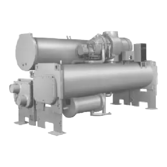
Hermetic Screw Liquid Chillers
With HCFC-22 and HFC-134a
NEVER APPLY an open flame or live steam to a refrigerant
cylinder. Dangerous over pressure can result. When it is necessary
to heat refrigerant, use only warm (110 F [43 C]) water.
DO NOT REUSE disposable (nonreturnable) cylinders or
attempt to refill them. It is DANGEROUS AND ILLEGAL. When
cylinder is emptied, evacuate remaining gas pressure, loosen
the collar, and unscrew and discard the valve stem. DO NOT
INCINERATE.
CHECK THE REFRIGERANT TYPE before adding refrigerant to
the machine. The introduction of the wrong refrigerant can cause
machine damage or malfunction.
Operation of this equipment with refrigerants other than those
cited herein should comply with ANSI/ASHRAE-15 (latest
edition). Contact Carrier for further information on use of this
machine with other refrigerants.
DO NOT ATTEMPT TO REMOVE fittings, covers, etc., while ma-
chine is under pressure or while machine is running. Be sure pres-
sure is at 0 psig (0 kPa) before breaking any refrigerant connection.
CAREFULLY INSPECT all relief valves, rupture discs, and other
relief devices AT LEAST ONCE A YEAR. If machine operates in
a corrosive atmosphere, inspect the devices at more frequent
intervals.
DO NOT ATTEMPT TO REPAIR OR RECONDITION any
relief valve when corrosion or build-up of foreign material (rust,
dirt, scale, etc.) is found within the valve body or mechanism. Re-
place the valve.
DO NOT install relief devices in series or backwards.
USE CARE when working near or in line with a compressed spring.
Sudden release of the spring can cause it and objects in its path to
act as projectiles.
DO NOT STEP on refrigerant lines. Broken lines can whip about
and release refrigerant, causing personal injury.
DO NOT climb over a machine. Use platform, catwalk, or staging.
Follow safe practices when using ladders.
USE MECHANICAL EQUIPMENT (crane, hoist, etc.) to lift or
move inspection covers or other heavy components. Even if com-
ponents are light, use mechanical equipment when there is a risk of
slipping or losing your balance.
BE AWARE that certain automatic start arrangements CAN
ENGAGE THE STARTER, TOWER FAN, OR PUMPS. Open the
disconnect ahead of the starter, tower fan and pumps. Shut off the
machine or pump before servicing equipment.
USE only repaired or replacement parts that meet the code require-
ments of the original equipment.
DO NOT VENT OR DRAIN waterboxes containing industrial brines,
liquid, gases, or semisolids without the permission of your process
control group.
DO NOT LOOSEN waterbox cover bolts until the waterbox has
been completely drained.
DOUBLE-CHECK that coupling nut wrenches, dial indicators, or
other items have been removed before rotating any shafts.
DO NOT LOOSEN a packing gland nut before checking that the
nut has a positive thread engagement.
PERIODICALLY INSPECT all valves, fittings, and piping for cor-
rosion, rust, leaks, or damage.
PROVIDE A DRAIN connection in the vent line near each pres-
sure relief device to prevent a build-up of condensate or rain
water.
Form 23XL-2SI
Pg 1
23XL
50/60 Hz
9-94
Replaces: 23XL-1SI
Advertisement
Table of Contents

Subscribe to Our Youtube Channel
Related Manuals for Carrier 23XL


Summary of Contents for Carrier 23XL
-
Page 1: Safety Considerations
ANSI/ASHRAE-15 (latest cordance with the latest edition of ANSI/ASHRAE 15 (American edition). Contact Carrier for further information on use of this National Standards Institute/American Society of Heating, machine with other refrigerants. -
Page 2: Table Of Contents
• INSTALL SPRING ISOLATION the nearest Carrier representative if any item is missing. Connect Piping ......18 3. - Page 3 FRONT VIEW 1 — Power Panel 2 — Local Interface Display (LID) Control Center 3 — ASME Nameplate, Cooler 4 — Cooler Refrigerant Isolation Valve 5 — ASME Nameplate, Economizer (Hidden) 6 — Service Valve 7 — Take-Apart Rabbet Fit Connector (Lower) 8 —...
-
Page 4: Rigging The Machine
FRONT VIEW 1 — Compressor Nameplate (Hidden) 2 — Power Panel 3 — Local Interface Display (LID) Control Center 4 — ASME Nameplate, Cooler 5 — Cooler 6 — Vessel Separation Feet 7 — Economizer Float Valve Access Cover (Hidden) 8 —... -
Page 5: Rig Machine Components
*Carrier recommends that ‘‘I’’ Beam Spreader Bars be field supplied and installed. NOTES: 1. Each chain must be capable of supporting the entire weight of the machine. Maxi- mum weight of machine is 13,200 lbs (5940 Kg). - Page 6 S30 x 464 S10 x 35 S25.4 x 511 W12 x 22 W30 x 321 W10 x 25 W25.4 x 365 †Carrier recommends that ‘‘I’’ beam spreader bars be field supplied and installed. Fig. 5 — Machine Rigging Guide (Frame 4 Machines)
- Page 7 23-22 A (LENGTH) OVERALL OVERALL NOZZLE PIPE SIZE HEAT EXCHANGER B (WIDTH) C (HEIGHT) (in.) 1 Pass 2 and 3 Pass* SIZE ft-in. ft-in. ft-in. ft-in. 1-Pass 2 and 3-Pass 10 or 11 4- 9 ⁄ 1454 6- 9 ⁄ 2073 2870 ⁄...
- Page 8 NOTES: 1. For flanged waterbox nozzles, refer to the certified drawings for length addition measurements. 2. Service access should be provided based on American Society of Heating, Refrigeration, and Air Conditioning Engineers (ASHRAE) 15, latest edition, National Fire Protection Association (NFPA) 70, and local safety codes. 3.
- Page 9 Table 1 — 23XL Compressor Weights Table 2 — 23XL Component Weights ASSEMBLY FRAME 1 AND 2 FRAME 4 23XL COMPRESSOR SIZE COMPONENT (Less Motor) UNIT (Tons) Oil Separator 1180 2880* 1306* Economizer† 2270 1029 Frame 1 Muffler 2300 1043 Discharge Piping: Frame 2 2400...
- Page 10 Table 5A — 23XL Waterbox Cover Weights (Frame 1 and 2 Machines)* FRAME 1 FRAME 2 WATERBOX HEAT EXCHANGER DESCRIPTION (kPa) NIH, 1 Pass NIH, 2 Pass (Plain) (1034) Cooler or NIH, 2 Pass (With Pipe Nozzles) Condenser NIH, 3 Pass (1034) LEGEND NIH —...
- Page 11 NOTE: Before proceeding with disassembly, make sure the 3. Separate compressor from oil supply system by discon- machine is at atmospheric pressure. necting the following: a. discharge flange from compressor and remove check NOTE: The screw compressor uses all metric dimensions valve (Fig.
- Page 12 Fig. 8 — 23XL Drive End View (Frame 1 and 2 Machines) Refer to Fig. 10 unless otherwise specified. c. optional economizer gas line to compressor rotors (Fig. 10). 1. Turn all 4 vessel separation feet to the lowered position (Fig.
- Page 15 2. Cover all openings. Additional Notes For Frame 1, 2, and 4 Machines: 3. Be sure the switches, sensor, and transducers are 1. Use silicon grease on new O-rings when refitting. disconnected. 2. Use gasket sealant on new gaskets when refitting. 4.
-
Page 16: Install Machine Supports
dictate the use of soleplates and leveling pads. Refer to Install Machine Supports Fig. 13-18. INSTALL STANDARD ISOLATION — Figures 13-18 show Level machine by using jacking screws in isolation sole- the position of support plates and shear flex pads that form plates. - Page 17 HRS — Hot Rolled Steel NOTES: 1. Dimensions in ( ) are in millimeters. 2. Accessory (Carrier supplied, field installed) soleplate package in- cludes 4 soleplates, 16 jacking screws and leveling pads. Re- quires accessory spring vibration isolation package. 3. Jacking screws to be removed after grout has set.
-
Page 18: Install Spring Isolation
For adequate and long-lasting machine support, proper grout 5. Water flow direction information is shown in Fig. 20 and selection and placement is essential. Carrier recommends that only epoxy-type grout be used for machine installation. Fol- NOTE: Entering water is always the lower of the two low manufacturer’s instructions in applying grout. - Page 19 Fig. 19 — Typical Nozzle Piping...
- Page 20 Cooler and Condenser Nozzle Arrangements NOZZLE ARRANGEMENT CODES Cooler Condenser Pass Code Pass Code Waterbox Nozzle Sizes NOMINAL PIPE ACTUAL PIPE SIZE (in.) ID (in.) FRAME PASS Cooler and Condenser Cooler and Condenser 6.065 6.065 6.065 7.981 6.065 6.065 LEGEND ID —...
- Page 21 Cooler and Condenser Nozzle Arrangements NOZZLE ARRANGEMENT CODES Cooler Condenser Pass Code Pass Code Waterbox Nozzle Sizes NOMINAL PIPE ACTUAL PIPE SIZE (in.) ID (in.) FRAME PASS Cooler and Condenser Cooler and Condenser 10.020 7.981 6.065 *Frame 4 waterboxes are factory fabricated with bolt-on covers. Fig.
- Page 22 DIMENSIONS ENGLISH (ft-in.) TANK SIZE 0428 10- 5 9-10 ⁄ ⁄ ⁄ 4-11 ⁄ 3- 8 ⁄ ⁄ ⁄ ⁄ ⁄ ⁄ ⁄ 0452 14-11 ⁄ 14- 4 ⁄ ⁄ ⁄ ⁄ ⁄ 7- 2 ⁄ 3-11 ⁄ ⁄ ⁄ ⁄...
- Page 23 LEGEND Hidden Piping Field Supplied and Installed Piping Factory Supplied and Installed Piping Fig. 23 — Typical Optional Pumpout System Piping Schematic with Storage Tank...
- Page 24 LEGEND Field Supplied and Installed Piping Factory Supplied and Installed Piping Fig. 24 — Typical Optional Pumpout System Piping Schematic without Storage Tank...
-
Page 25: Make Electrical Connections
VENT VALVE OIL RETURN LINE CONNECTION Do not run 120-v wiring into the control center. The control center should only be used for additional extra low-voltage wiring (50 v maximum). Wiring diagrams in this publication (Fig. 27-31) are for reference only and are not intended for use during actual installation;... -
Page 26: Connect Control Inputs
Additional spare sensors rotation. and Carrier Control Network modules may be specified as well. These are wired to the machine control center as in- dicated in Fig. 29-31. - Page 27 — Chilled Water Pump 2. All wiring must comply with applicable codes. — Condenser Water Pump 3. Refer to Carrier System Design Manual for details regarding piping techniques. — Disconnect 4. Wiring not shown for optional devices such as: —...
- Page 28 — Condenser Water Pump 2. All wiring must comply with applicable codes. — Chilled Water Pump 3. Refer to Carrier System Design Manual for details regarding piping techniques. — Disconnect 4. Wiring not shown for optional devices such as: —...
-
Page 29: Insulate Motor Terminals And Lead Wire Ends
Voltage to terminals LL1 and LL2 comes from a con- trol transformer in a starter built to Carrier specifi- cations. Do not connect an outside source of control power to the compressor motor starter (terminals LL1 and LL2). -
Page 30: Install Field Insulation
When connecting the CCN communication bus to a sys- 10. Cut another CCN wire and strip the ends of the tem element, a color code system for the entire network is conductors. recommended to simplify installation and checkout. The fol- 11. - Page 31 23XL CHILLER 23XL CHILLER 23XL CHILLER LEGEND Factory Wiring Field Wiring *Field supplied terminal strip must be located in the control center. Fig. 31 — Typical COMM1 CCN Communication Wiring for Multiple Chillers...
- Page 32 Fig. 32 — 23XL Insulation Area for Frame 1 and 2 Machines Fig. 33 — 23XL Insulation Area for Frame 4 Machines...
- Page 33 10 amps at 115 vac up to 3 amps at 600 II. POWER WIRING TO STARTER vac. Control wiring required for Carrier to start pumps and tower fan 2.0 Power conductor rating must meet minimum unit nameplate voltage motors must be provided to assure machine protection.
- Page 34 10 amps at 115 vac up to 3 amps at 600 vac. Control wiring required for Carrier to start pumps and tower fan motors must be provided to assure machine for a specific installation. Refer to certified field wiring diagrams for protection.
-
Page 35: Checklist
Other 8. The motor starter has not been supplied by Carrier. It has been installed according to the manufacturer’s instructions. 9. The motor starter has not been supplied by Carrier and it has been checked for proper operation. COMMENTS: CL-1... - Page 36 Concerns about the installation/request for additional assistance: I am aware that the start-up time for a Carrier chiller can take between 2 and 6 days depending on the model of the machine and the options and accessories used with it.
Need help?
Do you have a question about the 23XL and is the answer not in the manual?
Questions and answers