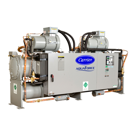
Carrier EVERGREEN 30HXA Installation Instructions Manual
6 series water-cooled and condenserless with comfortlink controls 50/60 hz
Hide thumbs
Also See for EVERGREEN 30HXA:
- Installation instructions manual (29 pages) ,
- Controls, start-up, operation, service, and troubleshooting (100 pages)
Table of Contents
Advertisement
CONTENTS
SAFETY CONSIDERATIONS . . . . . . . . . . . . . . . . . . . . . . . .1
INTRODUCTION . . . . . . . . . . . . . . . . . . . . . . . . . . . . . . . . . . . .1
INSTALLATION . . . . . . . . . . . . . . . . . . . . . . . . . . . . . . . . . . 1-41
Step 1 - Inspect Shipment . . . . . . . . . . . . . . . . . . . . . . . . 1
Step 2 - Rig and Place Unit . . . . . . . . . . . . . . . . . . . . . . . 16
Step 3 - Piping Connections . . . . . . . . . . . . . . . . . . . . . .16
PIPING
Step 4 - Make Electrical Connections . . . . . . . . . . . . .25
Step 5 - Install Accessories . . . . . . . . . . . . . . . . . . . . . . 27
Step 6 - Leak Test Unit . . . . . . . . . . . . . . . . . . . . . . . . . . . .27
Step 7 - Refrigerant Charge . . . . . . . . . . . . . . . . . . . . . . .40
• 30HXA UNITS
SAFETY CONSIDERATIONS
Installing, starting up, and servicing this equipment can
be hazardous due to system pressures, electrical components,
and equipment location. Only trained, qualified installers and
service mechanics should install, start up, and service this
equipment.
IMPORTANT: This equipment generates, uses, and can
radiate radio frequency energy. If not installed and used in
accordance with these instructions, this equipment may
cause radio interference. The equipment has been tested
and found to comply with the limits of a Class A comput-
ing device as defined by the FCC (Federal Communica-
tions Commission, U.S.A.) Regulations, Subpart J of Part
15, which are designed to provide reasonable protection
against such interference when operated in a commercial
environment.
When working on the equipment, observe precautions in the
literature, and on tags, stickers, and labels attached to the
equipment.
• Follow all safety codes.
• Wear safety glasses and work gloves.
• Use care in handling, rigging, and setting bulky
equipment.
Manufacturer reserves the right to discontinue, or change at any time, specifications or designs without notice and without incurring obligations.
Catalog No. 04-53300025-01
Liquid Chillers Series 6 with COMFORTLINK™ Controls
Installation Instructions
Page
Printed in U.S.A.
Form 30HX-13SI
30HXA,HXC076-271
Water-Cooled and Condenserless
INTRODUCTION
These instructions cover installation of 30HX liquid chillers
with electronic controls and units with factory-installed options
(FIOPs).
INSTALLATION
Step 1 - Inspect Shipment -
age upon arrival. If damage is found, immediately file a claim
with the shipping company. Verify proper unit delivery by
comparing the model number on the nameplate with the data in
Fig. 1. Do not store units in an area exposed to weather because
of sensitive control mechanisms and electronic devices.
30HXC 076 R - - 6 6 1 AA
Model Description
30HXA -
Condenserless
Liquid Chiller
30HXC -
Water-Cooled
Liquid Chiller
Nominal Size
076 126 186
086 136 206
096 146 246
106 161 261
116 171 271
Refrigerant/Cooler Options
L = Nitrogen with Minus 1-Pass Cooler
M = R-134a with Minus 1-Pass Cooler
N = Nitrogen with Standard Cooler
P = R-134a with Plus 1-Pass Cooler
Q = Nitrogen with Plus 1-Pass Cooler
R = R-134a with Standard Cooler
Electrical Options
- = Across The Line Start
A = Non-Fused Disconnect
Y = Y-Delta Starter
Z = Y-Delta and Non-Fused Disconnect
*Option Code Descriptions:1 = Minimum Load Control, 2 = Suction Service
Valve, and 3 = Medium Temperature Brine
Fig. 1 - 30HX Identification
Locate unit indoors. When considering unit location, con-
sult National Electrical Code (NEC, U.S.A.) and local code
requirements. Allow sufficient space for wiring, piping, and
service. Install unit in an area which will not be exposed to am-
bient temperatures below 50 F (10 C). See Fig. 2-10 for clear-
ance details.
Allow the following clearances for service access:
Front . . . . . . . . . . . . . . . . . . . . . . . . . . . . . . . . . . .3 ft (914 mm)
Rear. . . . . . . . . . . . . . . . . . . . . . . . . . . . . . . . . . . . .3 ft (914 mm)
Top . . . . . . . . . . . . . . . . . . . . . . . . . . . . . . . . . . . . .2 ft (610 mm)
Ends . . . . . . . . . . . . . . . . . . . . . . tube length at one (either) end;
Be sure surface beneath unit is level and is capable of
supporting the operating weight of the unit. See Fig. 11 and 12
and Tables 1A and 1B for unit mounting and operating
weights. If necessary, add supporting structure (steel beams or
reinforced concrete slabs) to floor to transfer weight to nearest
beams.
Pg 1
EVERGREEN
50/60 Hz
Inspect unit for dam-
Factory-Installed
Option Codes*
AA - 1
BA - 2
CA - 3
KA - 1,2
LA - 1,3
TA - 2,3
ZB - 1,2,3
Packaging Code
1 = Standard Domestic
2 = Standard Export
Series
Voltage Code
1 = 575-3-60
2 = 380-3-60
4 = 230-3-60
5 = 280/230-3-60
6 = 460-3-60
8 = 230-3-50
9 = 380/415-3-50
Display Options
- = Navigator Display
E = Navigator Display with
Energy Management
3 ft (914 mm) at opposite end.
Instructions continued on page 16.
10-08
Replaces: 30HX-12SI
®
Advertisement
Table of Contents

Related Manuals for Carrier EVERGREEN 30HXA


Summary of Contents for Carrier EVERGREEN 30HXA
-
Page 1: Table Of Contents
® EVERGREEN 30HXA,HXC076-271 Water-Cooled and Condenserless Liquid Chillers Series 6 with COMFORTLINK™ Controls 50/60 Hz Installation Instructions CONTENTS INTRODUCTION Page These instructions cover installation of 30HX liquid chillers SAFETY CONSIDERATIONS ......1 with electronic controls and units with factory-installed options (FIOPs). - Page 2 a30-4647...
- Page 3 a30-4648...
- Page 4 a30-4649...
- Page 11 5.00 (127.00) 0.88 3.25 (22.35) (82.55) 1.42 (36.07) 2.17 0.50 DIA (53.34) (4) HOLES 3.58 (90.93) NOTE: Dimensions shown in inches (mm). 30HX FOOT WEIGHT DISTRIBUTION AT EACH MOUNTING PLATE, 30HXC UNITS — lb (kg) MOUNTING PLATE NO. UNIT 30HXC 738 (335) 943 (428) 595 (270)
- Page 12 Table 1A — Physical Data, English UNIT SIZE 30HX UNIT OPERATING WEIGHT (lb) Water-Cooled (HXC) 5700 5723 5855 6177 6415 6465 6688 6718 Condenserless (HXA) 4717 4744 4835 5151 5163 5205 5309 5333 COMPRESSORS Semi-Hermetic, Twin Screw Quantity Nominal Capacity per Compressor (tons) 39/39 46/39 56/39...
- Page 13 Table 1A — Physical Data, English (cont) UNIT SIZE 30HX UNIT OPERATING WEIGHT (lb) Water-Cooled (HXC) 7452 7660 7854 10,581 10,969 10,992 11,029 Condenserless (HXA) 5752 5777 5946 7,485 7,621 7,621 7,621 COMPRESSORS Semi-Hermetic, Twin Screw Quantity Nominal Capacity per Compressor (tons) 80/56 66/80 80/80...
- Page 14 Table 1B — Physical Data, SI UNIT SIZE 30HX UNIT OPERATING WEIGHT (kg) Water-Cooled (HXC) 2586 2597 2657 2803 2911 2933 3034 3048 Condenserless (HXA) 2140 2152 2194 2337 2342 2362 2408 2420 COMPRESSORS Semi-Hermetic, Twin Screw Quantity Nominal Capacity per Compressor (kW) 137/137 162/137 197/137...
- Page 15 Table 1B — Physical Data, SI (cont) UNIT SIZE 30HX UNIT OPERATING WEIGHT (kg) Water-Cooled (HXC) 3381 3475 3564 4799 4976 4986 5003 Condenserless (HXA) 2610 2621 2698 3395 3457 3457 3457 COMPRESSORS Semi-Hermetic, Twin Screw Quantity Nominal Capacity per Compressor (kW) 281/197 232/281 281/281...
-
Page 16: Step 2 - Rig And Place Unit
Locate valves in return and supply fluid lines as close to the Step 2 — Rig and Place Unit chiller as possible. Locate air vent at highest point of the cooler fluid system. See Fig. 13. CAUTION Provide drain connections at all low points to permit Rig unit from the top heat exchanger only. - Page 17 a30-4653...
- Page 18 NOTES: 1. Piping shown is for general point-of-connection only and is not intended to show details for a specific installation. Certified field wiring and dimensional drawings are available upon request. The 30HXA units should be installed using certified drawings. 2. Refer to Tables 2 and 3 for 30HXA chiller/09DK condenser combination refrigerant line sizes. 3.
- Page 19 Table 2 — Refrigerant Line Sizes for 30HXA Chiller/09DK Condenser Combinations — Recommended Refrigerant Pipe Sizes (in. OD) TOTAL LENGTH OF INTERCONNECTING PIPING — FT (M) 30HXA UNIT SIZE 0-50 (0-15) 50-100 (15-30) 100-200 (30-60) Liquid Line* Discharge Line† Liquid Line* Discharge Line†...
- Page 20 Table 3 — Refrigerant Line Sizes for 30HXA Chiller/09DK Condenser Combinations — Double Discharge Riser Pipe Sizes (in. OD) RISER A* RISER B* 30HXA UNIT SIZE Total Length of Interconnecting Piping — FT (M)† 0-200 (0-60) 0-50 (0-15) 50-100 (15-30) 100-200 (30-60) LEGEND *Refer to Fig.
- Page 21 152.4 137.2 121.9 106.7 91.4 76.2 61.0 45.7 30.4 15.2 TONS COOLING kW COOLING NOTES: 1. Values are for a 2° F (1.1° C) pressure drop at 125 F (51.7 C) saturated discharge temperature, and 105 F (40.6 C) liquid refrigerant temperature. 2.
-
Page 22: 30Hxa Piping, Valve, And Fan Cycling Pressure Switch Installation
valve when brazing discharge line to avoid damaging the valve. Liquid line solenoid valves with manual lift stems should be installed between the field-supplied liquid line filter CONDENSER driers and the unit. For proper electrical connections see Fig. 18. If valves are installed in the liquid lines, it is recommended that field-supplied pressure relief valves be installed in each liquid line and the pressure setting should be 320 psig RED. -
Page 23: 30Hxc Piping And Valve Installation
field-supplied -in. (6.4 mm) copper line must be run connections on the condenser piping to reduce vibration trans- from the -in. NPT port on the back-pressure valve cap mission. Offset the piping to permit condenser head removal to the -in. SAE flare fitting on the motor cooling line. for maintenance purposes. - Page 24 a30-4650...
-
Page 25: Step 4 - Make Electrical Connections
Fig. 19 — 30HXA Units Back Pressure Valve Equalizer Line Connection (076-186 Sizes Shown) COMPRESSOR A1 CIRCUIT A COMPRESSOR A2 ECONOMIZER TRANSDUCER TO CIRCUIT A CIRCUIT A ECONOMIZER DISCHARGE CONNECTION LINE 1/4 IN. EQUALIZER LINE SEPARATOR CIRCUIT A BACK PRESSURE VALVES CIRCUIT A ECONOMIZER CONNECTION... -
Page 26: Field Control Power Connections
OPTIONAL BYPASS VALVE FOR NORMAL DUTY. BYPASS VALVE REQUIRED FOR BRINE BYPASS VALVE APPLICATIONS TO PREVENT CONDENSER FREEZE-UP. OUTLET 30HXC CONDENSER SENSOR INLET TEMPERATURE CONTROLLED VALVE OPTIONAL BYPASS VALVE FOR NORMAL DUTY. BYPASS VALVE REQUIRED FOR BRINE BYPASS VALVE APPLICATIONS TO PREVENT CONDENSER FREEZE-UP. SIGNAL CHILLER CONTROL PANEL OUTLET... -
Page 27: Condenser Fan Control For Condenser
Refer to unit of TB2 have been provided for a field-supplied circuit B fan Price Pages or contact your local Carrier representative control relay for a remote condenser (30HXA only). Use relays for more details. For installation details, refer to separate with a coil rating of 75-va. -
Page 28: 30Hxc Units
Table 6A — Unit Electrical Data, 30HXC Units UNIT VOLTAGE UNIT VOLTAGE CONTROL CIRCUIT POWER NO. POWER UNIT Supplied Rec Fuse Size V-Hz Supplied SUPPLY SUPPLY V-Hz 30HXC MOCP (Single QTY. REQD. CONDUCTORS (3 Ph) Min Max Min Max MOCP 230-60 198.7 —... - Page 29 Table 6A — Unit Electrical Data, 30HXC Units (cont) UNIT VOLTAGE UNIT VOLTAGE CONTROL CIRCUIT POWER NO. POWER UNIT Supplied Rec Fuse Size V-Hz Supplied SUPPLY SUPPLY V-Hz 30HXC MOCP (Single QTY. REQD. CONDUCTORS (3 Ph) Min Max Min Max MOCP 230-60 398.7...
- Page 30 Table 6B — Unit Electrical Data, 30HXA Units UNIT VOLTAGE UNIT VOLTAGE CONTROL CIRCUIT POWER NO. POWER UNIT Supplied Rec Fuse Size V-Hz Supplied SUPPLY SUPPLY V-Hz 30HXA MOCP (Single QTY. REQD. CONDUCTORS (3 Ph) Min Max Min Max MOCP 230-60 291.2 —...
- Page 31 Table 6B — Unit Electrical Data, 30HXA Units (cont) UNIT VOLTAGE UNIT VOLTAGE CONTROL CIRCUIT POWER NO. POWER UNIT Supplied Rec Fuse Size V-Hz Supplied SUPPLY SUPPLY V-Hz 30HXA MOCP (Single QTY. REQD. CONDUCTORS (3 Ph) Min Max Min Max MOCP 230-60 707.9...
- Page 32 Table 7A — Compressor Electrical Data, 30HXC Units COMPRESSOR NUMBERS NAMEPLATE UNIT SIZE 30HXC V-Hz (3 Phase) 208/230-60 230-60 460-60 44.3 44.3 076-XL 575-60 35.4 35.4 380-60 53.7 53.7 230-50 380/415-50 55.8 55.8 208/230-60 98.1 98.1 230-60 88.3 88.3 460-60 44.3 44.3 076-WD...
- Page 33 Table 7A — Compressor Electrical Data, 30HXC Units (cont) COMPRESSOR NUMBERS NAMEPLATE UNIT SIZE 30HXC V-Hz (3 Phase) 208/230-60 230-60 460-60 79.2 53.6 116-XL 575-60 63.3 42.8 380-60 95.9 64.9 230-50 380/415-50 97.8 67.7 208/230-60 175.4 118.6 230-60 157.9 106.7 460-60 79.2 53.6...
- Page 34 Table 7A — Compressor Electrical Data, 30HXC Units (cont) COMPRESSOR NUMBERS NAMEPLATE UNIT SIZE 30HXC V-Hz (3 Phase) 208/230-60 230-60 460-60 103.1 71.2 161-XL 575-60 82.4 56.9 380-60 124.8 86.2 230-50 380/415-50 128.6 88.2 208/230-60 228.8 157.6 230-60 205.5 141.8 460-60 103.1 71.2...
- Page 35 Table 7A — Compressor Electrical Data, 30HXC Units (cont) COMPRESSOR NUMBERS NAMEPLATE UNIT SIZE V-Hz 30HXC (3 Phase) 208/230-60 230-60 460-60 86.1 48.2 103.1 206-XL 575-60 68.8 38.6 82.4 380-60 104.2 58.4 124.8 230-50 380/415-50 105.8 55.8 128.6 208/230-60 190.6 106.8 228.8 230-60...
- Page 36 Table 7B — Compressor Electrical Data, 30HXA Units COMPRESSOR NUMBERS NAMEPLATE UNIT SIZE 30HXA V-Hz (3 Phase) 208/230-60 230-60 460-60 64.9 64.9 076-XL 575-60 51.9 51.9 380-60 78.7 78.7 230-50 380/415-50 81.5 81.5 208/230-60 143.8 143.8 230-60 129.4 129.4 460-60 64.9 64.9 076-WD...
- Page 37 Table 7B — Compressor Electrical Data, 30HXA Units (cont) COMPRESSOR NUMBERS NAMEPLATE UNIT SIZE 30HXA V-Hz (3 Phase) 208/230-60 230-60 460-60 115.4 77.6 116-XL 575-60 92.2 62.1 380-60 139.7 94.0 230-50 380/415-50 145.4 99.2 208/230-60 255.5 171.9 230-60 230.0 154.7 460-60 115.4 77.6...
- Page 38 Table 7B — Compressor Electrical Data, 30HXA Units (cont) COMPRESSOR NUMBERS NAMEPLATE UNIT SIZE 30HXA V-Hz (3 Phase) 208/230-60 230-60 460-60 157.9 1175 106.6 161-XL 575-60 126.2 85.1 380-60 191.2 1299 129.0 230-50 380/415-50 201.2 1265 133.4 1045 208/230-60 349.6 235.9 230-60 314.6...
- Page 39 Table 7B — Compressor Electrical Data, 30HXA Units (cont) COMPRESSOR NUMBERS NAMEPLATE UNIT SIZE V-Hz 30HXA (3 Phase) 208/230-60 230-60 460-60 129.6 73.1 157.9 1175 206-XL 575-60 103.6 58.5 126.2 380-60 156.9 1017 88.5 191.2 1299 230-50 380/415-50 161.7 1226 92.0 201.2 1265...
-
Page 40: 30Hxa Units
4. Check for a clear sight glass. If the unit is not fully R-134a only. DO NOT USE ANY OTHER REFRIGER- loaded, the sight glass may be flashing. This condition is ANT in these units without first consulting your Carrier normal for a partially loaded unit. If the unit is fully representative. - Page 41 Table 10 — 30HXA Estimated System Refrigerant Charge TOTAL LIQUID LINE COOLER CONDENSER PIPING AIR-COOLED REFRIGERANT REFRIGERANT REFRIGERANT CHARGE CHARGE CHARGE† 30HXA CONDENSER TYPE, CHARGE CIRCUIT PIPE SIZE SIZE (Qty)* (in. OD) 09DK 084 (1) 09DK 084 (1) 09DK 094 (1) 09DK 074 (1) and 09DK 044 (1) 09AZV102FE (1)
- Page 44 Copyright 2008 Carrier Corporation Manufacturer reserves the right to discontinue, or change at any time, specifications or designs without notice and without incurring obligations. Catalog No. 04-53300025-01 Printed in U.S.A. Form 30HX-13SI Pg 44 10-08 Replaces: 30HX-12SI...
Need help?
Do you have a question about the EVERGREEN 30HXA and is the answer not in the manual?
Questions and answers