Honeywell Sensepoint XCL Installation Manual
Fixed gas detector
Hide thumbs
Also See for Sensepoint XCL:
- Installation manual (42 pages) ,
- Quick start manual (6 pages) ,
- Quick start manual (6 pages)

Related Manuals for Honeywell Sensepoint XCL


Summary of Contents for Honeywell Sensepoint XCL
- Page 1 All manuals and user guides at all-guides.com Sensepoint XCL Fixed Gas Detector Installation Manual...
-
Page 2: About This Manual
All manuals and user guides at all-guides.com About This Manual This manual describes how to install and use the Sensepoint XCL gas detector and should be read by anyone who installs, operates, or maintains these products. Read and understand this manual in full before you install the product. -
Page 3: Table Of Contents
All manuals and user guides at all-guides.com Contents About This Manual Contents 1 Introduction 1.1 Features ....... . . 1.2 Appearance . - Page 4 All manuals and user guides at all-guides.com Contents Current Source/Sink Selection ....17 2.6 Wiring of Modbus Output Versions ....19 Modbus Connection .
- Page 5 All manuals and user guides at all-guides.com Contents E.2 IC Compliance ......51 E.3 R&TTE Compliance .
-
Page 6: Introduction
Mobile app: A mobile app is available to commission and maintain the Sensepoint XCL gas detector. Sensepoint XCL can be used either indoor or outdoors. If used outdoors, a sheltered location should be chosen, which is protected from direct sunlight and rain. -
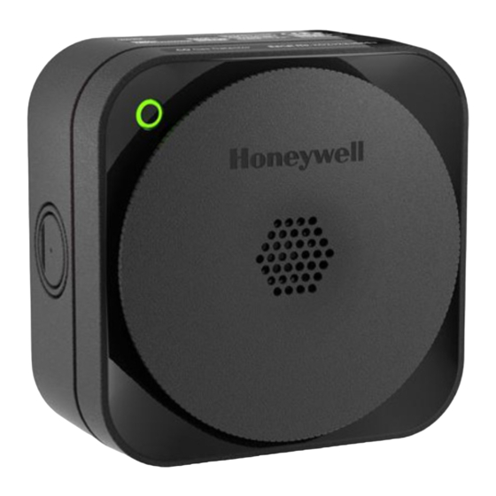
Page 7: Appearance
6) Status indicator 7) Gas sensor 8) Dust protection membrane 1.3 Accessories Part number Description SPXCLCAL Sensepoint XCL Calibration/Flow Cap SPXCLDMK Sensepoint XCL Duct Mount Kit SPXCLRGP Sensepoint Fixed Remote Gassing Port SPXCLGLD Sensepoint XCL M20 Cable Glands (10 pieces each pack) -
Page 8: Detectable Gases
All manuals and user guides at all-guides.com Introduction 1.4 Detectable Gases Sensepoint XCL is available for the detection of the following gases: Oxygen (O Toxic gases – Ammonia (NH – Carbon monoxide (CO) – Hydrogen (H – Hydrogen sulfide (H –... -
Page 9: Modbus Output Versions
All manuals and user guides at all-guides.com Introduction Modbus Output Versions NOTE Use of the mobile app is required to change the configuration settings of the Modbus RTU interface. 1) +24 V DC or 24 V AC 2) 0 V or 24 V AC 3) A 4) B 1.6 Relay Output... -
Page 10: Specifications
59 mm (2.3 in) Weight 500 g (1.1 lb) Power Supply Sensepoint XCL requires an isolated power supply unit that is certified by a national or international standard, such as UL. Nominal DC input voltage 24 V DC Nominal AC input voltage... -
Page 11: Outputs
All manuals and user guides at all-guides.com Introduction Outputs Analog output 0 to 22 mA sink or source (configurable) Digital output Modbus RTU Relay output 5 A, 250 V AC, 24 V DC The two relays can be used for fault signalling (normally energized) or for alarm signalling. -
Page 12: Operating Environment
Flammable catalytic versions: 10 to 90% RH. Operating the detector outside of this range may result drift and a decrease detector accuracy. Sensepoint XCL conforms to IP65, Type 4 (in accordance with NEMA 250) making it suitable for use in Pollution Degree 3 environments. -
Page 13: Installation
When Sensepoint XCL reaches the end of its life, it should be disposed of in accordance with local regulations. Do not use cleaning solvents or abrasives to clean the gas detector. -
Page 14: Installation Layout
Seek advice from experts where necessary. 2.3 Power Cable Specification Sensepoint XCL requires a power supply from the controller of specified supply voltage range in Section 1.7. Ensure that a minimum supply voltage is measured at the Sensepoint XCL, taking into account voltage... - Page 15 All manuals and user guides at all-guides.com Installation V+ detector V+ controller V detector V controller Controller Field Cable (L) V− detector V− controller The maximum loop resistance (R ) in the field cable is calculated loop max as follows: = (V −...
-
Page 16: Detector Module
All manuals and user guides at all-guides.com Installation 2.4 Detector Module 1) Inhibit switch 2) Status indicator 3) UP button 4) DOWN button 5) Current sink/source selection switch 6) Negative voltage output 7) Positive voltage output 2.5 Wiring of mA Output Versions Power Connection When connecting to DC power, make sure that the polarity is correct. -
Page 17: Inhibit Level Selection
All manuals and user guides at all-guides.com Installation Inhibit Level Selection Use the inhibit switch to set the level of current which is required when inhibit is active. 1) With this switch in the upper position, a current of 4 mA is output in inhibit mode. - Page 18 Installation Detector Source Mode with DC Power VIN+ 24 VDC VE− VIN− 4–20mA 4–20mA 1) System controller 2) Sensepoint XCL detector 3) Current flow Detector Sink Mode with DC Power VIN+ 24 VDC VE− VIN− 4–20mA 4–20mA 1) System controller 2) Sensepoint XCL detector 3) Current flow...
-
Page 19: Wiring Of Modbus Output Versions
2) Sensepoint XCL detector 3) System controller 4) Current flow 2.6 Wiring of Modbus Output Versions Modbus Connection For Modbus versions, up to 32 Sensepoint XCL detectors can be connected in a daisy chain arrangement as shown in the diagram below. -
Page 20: Cable Specification For Modbus Connection
All manuals and user guides at all-guides.com Installation NOTE Where possible, spur or ‘T’ connections should be avoided. Always keep the spur connection as short as possible. Cable Specification for Modbus Connection Type Cable Spec Max Length Modbus 0.5 mm to 2.5 mm twist pair shied cable 1000 m... -
Page 21: Securing The Back Box To A Wall
All manuals and user guides at all-guides.com Installation 2.7 Securing the Back Box to a Wall CAUTION Before starting installation, make sure that the system controller or external power source is switched off 1. There are four screw positions in the rear of the back box for mounting purposes. - Page 22 All manuals and user guides at all-guides.com Installation 2. Feed the cable through the cable gland. 3. Turn over the detector module and locate the terminal blocks on the back. Remove the terminal blocks by pulling them toward the center of the module.
-
Page 23: Ground Connections
All manuals and user guides at all-guides.com Installation 2.9 Ground Connections Effective grounding is crucial to ensure stable Modbus communications and to limit the effects of radio frequency interference. Ground points are provided inside the back box. In order to prevent false readings or alarms as a result of ground loops, ensure that the shield of all cables are grounded at a single point, preferably at the controller. -
Page 24: Securing The Detector Module To The Back Box
All manuals and user guides at all-guides.com Installation 2.10 Securing the Detector Module to the Back Box 1. Remove the front cover from the detector module to expose the four retaining screws as follows: a) Pull the flap on the bottom side to expose the remote gassing port and front cover locking feature. -
Page 25: Remote Gassing Connection
All manuals and user guides at all-guides.com Installation 4. Replace the front cover. Place the front cover into the detector module in the position shown and rotate it clockwise until it locks into position. 2.11 Remote Gassing Connection NOTE Use the remote gassing connection for bump test only. Perform calibrations using the calibration cap accessory. -
Page 26: Commissioning
Chapter Commissioning NOTE The Sensepoint XCL gas detector is supplied from the factory pre-calibrated. However, it is strongly recommended that the detector response is checked and if necessary, re-calibrated before placing it into service. Refer to Calibration on page 34 for details on the correct calibration procedure. - Page 27 All manuals and user guides at all-guides.com Commissioning 2. Remove the detector module of Sensepoint XCL. 3. Configure the sink/source mode of the detector. Refer to Current Source/Sink Selection on page 17 on details of how to do this. 4. Configure the required inhibit level of the detector.
-
Page 28: Status Indicator
7. Remove power and refit the detector module to the back box. 8. Refit the front cover. 9. Apply power. The Sensepoint XCL will enter a warm-up mode during which time the status indicator will be steady yellow and the output (mA version) will be held in an inhibited state. - Page 29 All manuals and user guides at all-guides.com Commissioning Warning: The indicator alternatively flashes green and yellow when the gas detector is in a warning state. Fault: The indicator flashes yellow when the gas detector is in a fault state. Inhibited: The indicator is on steady yellow when the user has placed the detector into the inhibit state for maintenance or repair.
-
Page 30: Maintenance
All manuals and user guides at all-guides.com Chapter Maintenance 4.1 Using the Control Buttons It is possible to perform basic maintenance functions on the Sensepoint XCL gas detector without the use of the mobile app. This is achieved through the use of two control buttons inside the detector. Familiarize yourself fully on the operation of these buttons before attempting to use them. -
Page 31: Maintenance Status Indicator
All manuals and user guides at all-guides.com Maintenance To escape and discard all changes: This escape function can be used at any time during the procedures detailed in the following sections. Press and hold the DOWN button for 5 seconds. 4.2 Maintenance Status Indicator There is another indicator on the rear of the detector module for easier maintenance. -
Page 32: Calibration Cap
All manuals and user guides at all-guides.com Maintenance Calibration gas purge While the calibration gas is purged, the indicator is on steady yellow Cancel When a task is cancelled, the indicator flashes yellow with three short pauses. 4.3 Calibration Cap The following table shows the recommended flow rate and stabilization time for each of the gas types. - Page 33 All manuals and user guides at all-guides.com Maintenance 1. Remove the front cover. a) Pull the flap on the bottom side to open it. b) Insert a thin, straight tool, such as a small screwdriver, into the hole to the right of the remote gassing port.
-
Page 34: Calibration
All manuals and user guides at all-guides.com Maintenance 5. Refer to the regulator manufacturer for instructions on how to start and stop the gas flow from the cylinder. CAUTION Always use a gas cylinder that is within its expiration date. 4.4 Calibration NOTE On versions that feature the Bluetooth®... - Page 35 All manuals and user guides at all-guides.com Maintenance the calibration cap. For details about how to use a calibration cap, see Calibration Cap on page 32. c) Apply fresh air to the detector, and wait for a few minutes until the reading is stable.
-
Page 36: Bump Test
All manuals and user guides at all-guides.com Maintenance c) Make sure that the reading voltage out returns to zero. If there is any doubt that the detector is not in fresh air, apply cylinder air. Otherwise, an alarm may occur. 6. -
Page 37: Replacing The Sensor
Do not replace the sensor without first a) removing power to the Sensepoint XCL or b) placing the sensor into the sensor maintenance mode. Connect your smartphone to the Sensepoint XCL via Bluetooth. Tap the Maintenance button and select Change Sensor. Follow the on-screen instructions. -
Page 38: Resetting Alarms And Faults
All manuals and user guides at all-guides.com Maintenance 3. Remove the sensor cover. a) Loosen the screw on the top of the sensor cover. b) Holding the screw, tilt it downwards from the upper edge of the cover. 4. Pull out the gas sensor to remove it. 5. -
Page 39: Mobile App
Mobile App Use the Sensepoint app to allow your smart device to connect to Sensepoint XCL. This mobile app makes it much easier to configure and maintain Sensepoint XCL detectors. The general procedure of using the mobile app is as follows: 1. -
Page 40: A Detector Parameters
All manuals and user guides at all-guides.com Appendix Detector Parameters... - Page 41 All manuals and user guides at all-guides.com Non-Bluetooth Versions (not available in all countries) User Selectable User Selectable Accuracy Response Time Detector Type Default Range Steps Default Cal Point Resolution Range Cal Gas Range t90 (s) ( ppm or % of applied gas which is the greater) Oxygen SPLLO1...
- Page 42 All manuals and user guides at all-guides.com Bluetooth Versions User Selectable User Selectable Accuracy Response Time Detector Type Default Range Steps Default Cal Point Resolution Range Cal Gas Range t90 (s) ( ppm or % of applied gas which is the greater) Oxygen SPLCO1...
- Page 43 All manuals and user guides at all-guides.com Detector Parameters NOTE Performance figures are based on the following: The humidity of the test gas is 50% RH. The performance values given are valid between 10% and 90% RH. Are measured using test units calibrated at 50% of full scale, Measurements are based on gas being applied using the calibration adapter at a rate of 300 ml/min for a period of 3 minutes (oxygen, flammable (CAT), carbon monoxide, hydrogen...
-
Page 44: B Troubleshooting
All manuals and user guides at all-guides.com Appendix Troubleshooting B.1 Warning Description Troubleshooting Warning 1 Calibration Overdue Calibrate the unit Warning 3 BLE failure (BLE version only) Power-cycle the unit. If same warning occurs again, contact manufacturer Warning 4 Time/date not set (RTC not set) / RTC reset Configure unit time. -
Page 45: C Ordering Information
SPLLF6XAXCXNZZ Sensepoint XCL Transmitter, Compliance, Safe Area, IP65, CH (CAT), 4–20 mA, Charcoal SPLLC1XAXCXNZZ Sensepoint XCL Transmitter, Compliance, Safe Area, IP65, CO (L), 4–20 mA, Charcoal SPLLC2XAXCXNZZ Sensepoint XCL Transmitter, Compliance, Safe Area, IP65, CO (H), 4–20 mA, Charcoal SPLLH1XAXCXNZZ Sensepoint XCL Transmitter, Compliance, Safe Area, IP65, H S (L), 4–20 mA, Charcoal... - Page 46 , Modbus, Relay, White SPLCC1BAXCXNZZ Sensepoint XCL Transmitter, Safe Area, IP65, CO, 4–20 mA, Charcoal SPLCC1BARCXNZZ Sensepoint XCL Transmitter, Safe Area, IP65, CO, 4–20 mA, Relay, Charcoal SPLCC1BAXWXNZZ Sensepoint XCL Transmitter, Safe Area, IP65, CO, 4–20 mA, White SPLCC1BARWXNZZ Sensepoint XCL Transmitter, Safe Area, IP65, CO, 4–20 mA, Relay, White...
-
Page 47: Accessories
Sensepoint XCL Transmitter, Safe Area, IP65, CH (CAT), Modbus, Relay, White SPLCC1BAXCXLZZ Sensepoint XCL Transmitter, Safe Area, IP65, CO, 4–20 mA, Charcoal, CoLA SPLCC1BARCXLZZ Sensepoint XCL Transmitter, Safe Area, IP65, CO, 4–20 mA, Relay, Charcoal, CoLA C.2 Accessories Part number Description SPXCLCAL... -
Page 48: Consumables
SPXCLRLG1SS Sensepoint XCL/XRL Replacement Sensor, H SPXCLRLN1SS Sensepoint XCL/XRL Replacement Sensor, NO SPXCLRLA1SS Sensepoint XCL Replacement Sensor, NH SPXCLFLT Sensepoint XCL Replacement Sensor Filter (10 pieces each pack) C.4 Spares Part number Description SPXCLSK1 Sensepoint XCL Service Kit SPXCLSCC Sensepoint XCL Sensor Cover, Charcoal... -
Page 49: D Warranty
Please contact your local Honeywell Analytics Service representative to register your claim. This is a summary. For full warranty terms please refer to the Honeywell Analytics’ General Statement of Limited Product Warranty, which is available on request. -
Page 50: E Safety Information For Wireless Devices
All manuals and user guides at all-guides.com Appendix Safety Information for Wireless Devices E.1 FCC Compliance This device complies with part 15 of the FCC Rules. Operation is subject to the following two conditions: (1) This device may not cause harmful interference, and (2) this device must accept any interference received, including interference that may cause undesired operation. - Page 51 2) This device must accept any interference, including interference that may cause undesired operation of the device E.3 R&TTE Compliance Hereby, Honeywell Analytics Asia Pacific Co., Ltd. declares that this gas detector, Sensepoint XCL, is in compliance with the essential requirements and other relevant provisions of Directive 1999/5/EC.
- Page 52 All manuals and user guides at all-guides.com Appendix Certification Electrical Safety UL 61010-1 CSA C22.2 No. 61010-1 IEC/EN 61010-1 Electromagnetic Compatibility EN 50270:2015 Radio R&TTE BT SIG Enclosure Protection IP65 Type 4 in accordance with NEMA 250 Gas Performance UL 2075 (CH and CO)
- Page 53 Tel: +41 (0)44 943 4300 Fax: +41 (0)44 943 4398 gasdetection@honeywell.com Asia Pacific, India Honeywell Analytics Asia Pacific, Co., Ltd. 7F Sangam IT Tower, 434 World Cup Buk-ro, Mapo-gu, Seoul 03922, South Korea Tel: +82 (0)2 6909 0300 Fax: +82 (0)2 2025 0388 India Tel: +91 124 4752700 analytics.ap@honeywell.com...
- Page 54 All manuals and user guides at all-guides.com Keep this manual for later use. 3017M5002_1 HAA170019 © 2017 Honeywell Analytics...
Need help?
Do you have a question about the Sensepoint XCL and is the answer not in the manual?
Questions and answers