
Related Manuals for Daikin FXUA50AVEB


Summary of Contents for Daikin FXUA50AVEB
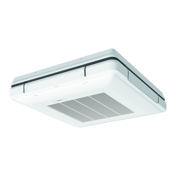
- Page 1 Installation and operation manual VRV system air conditioner FXUA50AVEB Installation and operation manual FXUA71AVEB English VRV system air conditioner FXUA100AVEB...
- Page 2 4P686644-3...
- Page 3 4P686644-4...
-
Page 4: Table Of Contents
Daikin website (publicly accessible). 13.2 Connecting the refrigerant piping ..........20 ▪ The full set of latest technical data is available on the Daikin 13.2.1 To connect the refrigerant piping to the indoor unit ..20 Business Portal (authentication required). -
Page 5: Specific Installer Safety Instructions
Make sure installation, servicing, maintenance, repair and applied materials follow the instructions from Daikin and, in WARNING addition, comply with applicable legislation and are performed by qualified persons only. In Europe and areas ▪ If the power supply has a missing or wrong N-phase, where IEC standards apply, EN/IEC 60335-2-40 is the equipment might break down. -
Page 6: Instructions For Equipment Using R32 Refrigerant
▪ Do NOT re-use joints and copper gaskets which have been used already. Make sure installation, servicing, maintenance and repair comply with instructions from Daikin and with applicable ▪ Joints made in installation between parts of refrigerant legislation and are executed ONLY by authorised persons. -
Page 7: Instructions For Safe Operation
3 User safety instructions ▪ Batteries are marked with the following symbol: WARNING This appliance can be used by children aged from 8 years and above and persons with reduced physical, sensory This means that the batteries may NOT be mixed with unsorted household waste. - Page 8 3 User safety instructions Maintenance and service (see "7 Maintenance and WARNING service" [ 4 11]) This unit contains electrical and hot CAUTION: Pay attention to the fan! parts. It is dangerous to inspect the unit while WARNING the fan is running. Before operating the unit, be sure the Make sure to turn OFF the main switch installation has been carried out...
-
Page 9: About The System
4 About the system location of the terminals, see the ▪ Do NOT use the unit until a service warning label for persons performing person confirms that the part from service and maintenance. which the refrigerant leaked has been repaired. CAUTION WARNING Turn off the unit before cleaning the... -
Page 10: System Layout
5 User interface System layout Operation INFORMATION Operation range The following illustration is an example and might NOT match your system layout. INFORMATION For the operation limits see the technical data of the connected outdoor unit. About operation modes INFORMATION Depending on the installed system, some operation modes will not be available. -
Page 11: Special Heating Operation Modes
7 Maintenance and service Automatic airflow control 6.2.2 Special heating operation modes Cooling Heating Operation Description ▪ When the room temperature is ▪ When starting operation. Defrost To prevent a loss of heating lower than controller's ▪ When the room temperature is capacity due to frost setpoint for cooling operation higher than the controller's... -
Page 12: Cleaning The Unit Exterior, Air Filter And Suction Grille
7 Maintenance and service 7.2.1 To clean the exterior CAUTION After a long use, check the unit stand and fitting for WARNING damage. If damaged, the unit may fall and result in injury. indoor unit wet. Possible NOTICE consequence: Electrical shock or fire. Do NOT wipe the controller operation panel with benzine, Clean with a soft cloth. -
Page 13: To Clean The Suction Grille
7 Maintenance and service 4 Dry the air filter in the shadow. WARNING 5 Reattach the air filter and close the suction grille. The appliance shall be stored in a room without continuously operating ignition sources (example: open 6 Turn ON the power. flames, an operating gas appliance or an operating electric 7 To remove warning screens, see the reference guide of the heater). -
Page 14: Troubleshooting
8 Troubleshooting ▪ No refrigerant leakage detected. Result: The system resumes Malfunction Measure normal operation after approximately 2 minutes. If water leaks from the unit. Stop operation. ▪ Refrigerant leakage detected. Result: The operation switch does NOT function Turn OFF the power properly. -
Page 15: Unit Installation
12 Unit installation Washer for hanger bracket ▪ Airflow directions. Choose the air discharge pattern according to Tie wraps the installation location. In case of 2-way and 3-way air discharge, Clamp washer setting" [ 4 23]. field setting is required. See "17.1 Field Insulation piece: Large (gas pipe) Insulation piece: Small (liquid pipe) -
Page 16: Mounting The Indoor Unit
12 Unit installation hanger bracket. Attached clamp washer (accessory) can be used to prevent the washer for hanger bracket (accessory) from falling during installation. Remove the clamp washer after the unit is mounted. A: ≥1500 A: ≥30 Clamp washer (accessory) Washer for hanger bracket (accessory) (mm) a:950... - Page 17 12 Unit installation Piping part Level NOTICE Do NOT install the unit tilted. Possible consequence: If the unit is tilted against the direction of the condensate flow (the drain piping side is raised), the float switch might malfunction and cause water to drip. Transportation tape To block the air outlet for 2-way or 3-way air discharge...
-
Page 18: Guidelines When Installing The Drain Piping
12 Unit installation Fix the blocking pad to the air outlet. ▪ General guidelines ▪ Connecting the drain piping to the indoor unit ▪ Checking for water leaks General guidelines ▪ Pipe length. Keep drain piping as short as possible. ▪... - Page 19 12 Unit installation To connect the drain piping to the indoor unit To check for water leaks The procedure differs depending on whether installation of the NOTICE system is already completed. When installation of the system is not Incorrect connection of the drain hose might cause leaks, yet completed, temporarily connect the user interface and power and damage the installation space and surroundings.
-
Page 20: Piping Installation
13 Piping installation If the temperature is higher than 30°C and the humidity is higher Piping installation than RH 80%, the thickness of the insulation materials should be at least 20 mm to prevent condensation on the surface of the insulation. 13.1 Preparing refrigerant piping 13.2... -
Page 21: Electrical Installation
14 Electrical installation Component Class Turn up the seams of the insulation pieces. Attach to the base of the unit. Tighten the tie wrap on the insulation pieces. User interface cable 0.75 to 1.25 mm (2‑core wire) Wrap the sealing pad from the base of the unit to the top of the flare nut. -
Page 22: Finishing The Indoor Unit Installation
15 Finishing the indoor unit installation User interface Most downstream indoor unit NOTICE Group control connection is NOT allowed. CAUTION ▪ Each indoor unit has to be connected to a separate user interface. Only a safety system compatible remote controller can be used as the user interface. See technical data sheet for remote controller compatibility 60~80 (e.g. -
Page 23: To Close The Suction Grille
Next commissioning instructions in this chapter, a general Configuration commissioning checklist is also available on the Daikin Business Portal (authentication required). 17.1 Field setting The general commissioning checklist is complementary to the instructions in this chapter and can be used as a... - Page 24 17 Configuration Setting: Thermostat differential changeover (if remote sensor is If the distance to the floor is (m) Then used) FXUA50+71 FXUA100 — If the system contains a remote sensor, set the increase/decrease ≤2.7 ≤3.2 13 (23) increments. 2.7<x≤3.0 3.2<x≤3.6 If you want to change increments to…...
-
Page 25: Technical Data
▪ A subset of the latest technical data is available on the regional Daikin website (publicly accessible). Connector (frame ground) Harness ▪ The full set of latest technical data is available on the Daikin Business Portal (authentication required). H*P, LED*, V*L Pilot lamp, light emitting diode Light emitting diode (service 18.1... - Page 26 18 Technical data Symbol Meaning Compressor motor Fan motor Drain pump motor Swing motor MR*, MRCW*, MRM*, MRN* Magnetic relay Neutral n=*, N=* Number of passes through ferrite core Pulse-amplitude modulation PCB* Printed circuit board Power module Switching power supply PTC* PTC thermistor Insulated gate bipolar transistor...
- Page 28 3P668115-2C 2022.01 Verantwortung für Energie und Umwelt...
Need help?
Do you have a question about the FXUA50AVEB and is the answer not in the manual?
Questions and answers