Daikin FXUQ PVJU Series Engineering Data

Daikin FXUQ PVJU Series Engineering Data

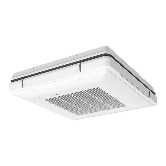
4-way blow ceiling-suspended type

Advertisement

EDUS391437-F15
FXUQ-PVJU
4-Way Blow
Ceiling-Suspended Type

Advertisement

Table of Contents
loading
Need help?

Need help?

Do you have a question about the FXUQ PVJU Series and is the answer not in the manual?

Questions and answers

Subscribe to Our Youtube Channel

Summary of Contents for Daikin FXUQ PVJU Series

  • Page 1 EDUS391437-F15 FXUQ-PVJU 4-Way Blow Ceiling-Suspended Type...
  • Page 3: Table Of Contents

    EDUS391437-F15 FXUQ-PVJU 4-Way Blow Ceiling-Suspended Type 1. Features and Benefits .................2 2. Specifications ....................3 3. Dimensions ....................5 4. Piping Diagrams..................6 5. Wiring Diagrams..................7 6. Electric Characteristics................8 7. Safety Devices Setting ................9 8. Capacity Tables ..................10 8.1 Cooling Capacity at Te: 43°F (6°C) ............10 8.2 Heating Capacity ..................
  • Page 4: Features And Benefits

    Features and Benefits EDUS391437-F15 1. Features and Benefits The unique 4-way ceiling-suspended cassette is an ideal solution for rooms without a false ceiling, or minimal space above a false ceiling, where adaptive comfort control is preferred. The optional Sensor Kit (occupancy and surface temperature) together with air temperature sensor and advanced control functions enables the unit to provide an exceptional comfort level, energy efficiency, and flexibility.
  • Page 5: Specifications

    EDUS391437-F15 Specifications 2. Specifications 4-Way Blow Ceiling-Suspended Type Model FXUQ18PVJU FXUQ24PVJU Power supply 1 phase, 60Hz, 208/230V 1 phase, 60Hz, 208/230V Btu/h 1 3 Cooling capacity 18,000 (5.3) 24,000 (7.0) (kW) Btu/h 2 3 Heating capacity 20,000 (5.9) 27,000 (7.9) (kW) Casing / Color Resin/Fresh White...
  • Page 6 Specifications EDUS391437-F15 4-Way Blow Ceiling-Suspended Type Model FXUQ30PVJU FXUQ36PVJU Power supply 1 phase, 60Hz, 208/230V 1 phase, 60Hz, 208/230V Btu/h 1 3 Cooling capacity 30,000 (8.8) 36,000 (10.6) (kW) Btu/h 2 3 Heating capacity 34,000 (10.0) 40,000 (11.7) (kW) Casing / Color Resin/Fresh White Resin/Fresh White 7-13/16×37-3/8×37-3/8...
  • Page 7: Dimensions

    EDUS391437-F15 Dimensions 3. Dimensions FXUQ18PVJU / FXUQ24PVJU / FXUQ30PVJU / FXUQ36PVJU FXUQ-PVJU...
  • Page 8: Piping Diagrams

    Piping Diagrams EDUS391437-F15 4. Piping Diagrams FXUQ18PVJU / FXUQ24PVJU / FXUQ30PVJU / FXUQ36PVJU C: 4D034245K Unit: in. (mm) Model Liquid φ1/2 φ1/4 FXUQ18PVJU (12.7) (6.4) φ5/8 φ3/8 FXUQ24PVJU / FXUQ30PVJU / FXUQ36PVJU (15.9) (9.5) FXUQ-PVJU...
  • Page 9: Wiring Diagrams

    EDUS391437-F15 Wiring Diagrams 5. Wiring Diagrams FXUQ18PVJU / FXUQ24PVJU / FXUQ30PVJU / FXUQ36PVJU FXUQ-PVJU...
  • Page 10: Electric Characteristics

    Electric Characteristics EDUS391437-F15 6. Electric Characteristics FXUQ18PVJU / FXUQ24PVJU / FXUQ30PVJU / FXUQ36PVJU 4D090214A FXUQ-PVJU...
  • Page 11: Safety Devices Setting

    EDUS391437-F15 Safety Devices Setting 7. Safety Devices Setting Model FXUQ18PVJU FXUQ24PVJU FXUQ30PVJU FXUQ36PVJU Printed circuit board fuse 250V 3.15A 250V 3.15A 250V 3.15A 250V 3.15A Drain pump °F – – – – thermal fuse (°C) Fan motor thermal °F – –...
  • Page 12: Capacity Tables

    Capacity Tables EDUS391437-F15 8. Capacity Tables Cooling Capacity at Te: 43°F (6°C) Indoor air temp. °FWB (Te: 43°F (6°C)) Capacity Model indication FXUQ18PVJU 14.2 11.8 16.1 12.9 18.0 13.7 18.4 13.6 18.6 13.0 18.9 12.8 FXUQ24PVJU 19.0 15.4 21.5 16.9 24.0 18.0 24.5...
  • Page 13: Sound Levels (Reference Data)

    EDUS391437-F15 Sound Levels (Reference Data) 9. Sound Levels (Reference Data) FXUQ18PVJU / FXUQ24PVJU 4D090216A FXUQ-PVJU...
  • Page 14 Sound Levels (Reference Data) EDUS391437-F15 FXUQ30PVJU / FXUQ36PVJU 4D090215A FXUQ-PVJU...
  • Page 15: Center Of Gravity

    EDUS391437-F15 Center of Gravity 10. Center of Gravity FXUQ18PVJU / FXUQ24PVJU / FXUQ30PVJU / FXUQ36PVJU Unit: in. (mm) 4D090212 FXUQ-PVJU...
  • Page 16: Installation Manual

    Installation Manual EDUS391437-F15 11. Installation Manual FXUQ18PVJU / FXUQ24PVJU / FXUQ30PVJU / FXUQ36PVJU SAFETY CONSIDERATIONS WARNING Read these SAFETY CONSIDERATIONS for Installation carefully before installing air conditioning equipment. After tion work. Installation must be done in accordance completing the installation, make sure that the unit operates with this installation manual.
  • Page 17 EDUS391437-F15 Installation Manual Do not touch the refrigerant pipes during and imme- diately after operation as the refrigerant pipes may be hot or cold, depending on the condition of the refriger- or gasoline are handled. Operating the unit in such sor, and other refrigerant cycle parts.
  • Page 18: Before Installation

    Installation Manual EDUS391437-F15 FXUQ18PVJU FXUQ24PVJU Installation manual FXUQ30PVJU VRV SYSTEM Air Conditioners FXUQ36PVJU ACCESSORIES CONTENTS Check if the following accessories are attached to the indoor unit. SAFETY CONSIDERATIONS.........[i] [ii] 1. BEFORE INSTALLATION ..........1 (1) Drain (2) Metal (3) Washer for Name (4) Clamp hose...
  • Page 19: Selection Of Installation Location

    EDUS391437-F15 Installation Manual OPTIONAL ACCESSORIES Check Items to be checked For this indoor unit, the remote controller is separately column required. Refer to the installation manual attached to the remote program dry and automatic (cooling/heating) given in the controller for how to install. If you set the fan speed at thermostat OFF, did you CARRY OUT THE WORK GIVING CAUTION TO THE FOLLOWING ITEMS AND AFTER THE WORK IS...
  • Page 20: Preparation Before Installation

    Installation Manual EDUS391437-F15 (NOTE 1) Exhaust (Discharge pattern) (Views from the ceiling) Lighting Indoor unit Indoor unit 4-way discharge 3-way discharge Discharge 60 (1500) or more 60 (1500) 80 (2000) or more or more Distance between indoor units 160 (4000) or more Fig.
  • Page 21 EDUS391437-F15 Installation Manual Make holes for hanging bolts, piping outlet, drain 37-3/8 (950) [unit: in. (mm)] piping outlet and electric wiring inlet. 32-7/8 (835) (hanging bolt pitch) Use the installation pattern paper (11) which shows the above hole locations. Determine the locations of hanging bolts, piping outlet, drain piping outlet and electric wiring inlet.
  • Page 22 Installation Manual EDUS391437-F15 Hanger Hanger Bend the horizontal blade and pull it out. Hanger Fig. 9 When carrying the indoor unit, hold it by the hanging metal (Refer to Fig. 9) Claw parts discharge Turn the horizontal For 2-way air discharge, in addition to the attached block- Bearing blade backward.
  • Page 23 EDUS391437-F15 Installation Manual Check that the sheet metal section of the blocking ma- terial is not protruding from the end of the lower decora- tion panel. Blocking material Insert Securely fix the blocking material and the indoor unit so that no clearance remains. Insert If clearance remains, it may cause air leakage and condensation.
  • Page 24: Installation Of The Indoor Unit

    Installation Manual EDUS391437-F15 * If the blocking material is difficult to insert, loosen the left (3) Check the level of the unit from 2 directions (air outlet and right screws of the lower decoration panel and insert it. Make sure to tighten the loosened screws again after the Hanging bolt (Field supply) Lower decoration panel...
  • Page 25: Refrigerant Piping Work

    EDUS391437-F15 Installation Manual Install the indoor unit leveled. Refrigerant piping can be connected from 3 directions. If the unit is inclined and the drain piping side gets high, In case of upward piping, remove the piping penetration cover, make holes for penetrating piping by cutting the water leakage.
  • Page 26 Installation Manual EDUS391437-F15 Table 1 After leak test, referring to , insulate both the gas and liquid piping connection with the attached joint Piping Tightening Dimension for insulating material (6) and (7) to prevent the piping from size torque Flare shape [in.
  • Page 27: Drain Piping Work

    EDUS391437-F15 Installation Manual When carrying out upward and rightward piping, use the NOTE attached L-shaped piping, and insulate the 2 places of connection. that makes one feel like breeze and can be obtained bender with radius is 1-9/16 in. (40 mm) or less. through a pressure reducing valve.
  • Page 28 Installation Manual EDUS391437-F15 If drain stagnates in the drain piping, the piping may be clogged. Metal clamp (2) Install supports at a distance of 3 to 5 feet (1 to 1.5 m) so (accessory) that the piping does not get clogged. Drain hose (1) (for connection to VP20) (accessory)
  • Page 29 EDUS391437-F15 Installation Manual If the drain riser is installed inclined, the float switch < In case of bending the tip > may malfunction and cause water leakage. Tightened part Make sure to use the drain hose (1), the elbow (10) and the sealing material (Large) (8) attached to the indoor unit as accessories.
  • Page 30: Electric Wiring Work

    Installation Manual EDUS391437-F15 smoothly. outlet (3) into the drain pan giving caution to avoid splashing water on the electric components such as drain pump. If the air outlet (3) is closed, pour water from the air (3) into the drain pan giving caution to avoid outlet (2).
  • Page 31 EDUS391437-F15 Installation Manual ELECTRICAL CHARACTERISTICS Connection of 2 Connection of 2 Connection of wirings of same wirings on one side wiring of different Indoor units Power supply Fan motor size must be is prohibited. sizes is prohibited. Voltage carried out on both Model Volts MCA MOP...
  • Page 32 Installation Manual EDUS391437-F15 Conduit mounting Make sure to install the conduit Mounting screw (18) wiring. Tab of conduit mounting plate Conduit mounting Slot Insert the tab of conduit mounting plate to slot. Power supply wiring · Ground wiring Transmission wiring Remote controller wiring Fig.
  • Page 33 EDUS391437-F15 Installation Manual CAUTION FOR MENDING THE COVER remote controllers control > In case the cover for penetrating piping is cut off and used Note: It is not necessary to designate indoor as wiring penetrating hole, after the wiring connection is unit address when using group control.
  • Page 34 Installation Manual EDUS391437-F15 FOR REMOTE CONTROL (FORCED OFF OR ON/OFF OPERATION) REMOTE CONTROLLERS) For control with 2 remote controllers, set one remote con- troller as main and the other remote controller as sub. input to the terminals T1 and T2 on the terminal block for remote controller and transmission wiring.
  • Page 35: Mounting Corner Cover · Suction Grille

    EDUS391437-F15 Installation Manual MOUNTING CORNER COVER · SUC- After attaching the suction grille in opposite order men- tioned in the clause “3. PREPARATION BEFORE INSTAL- TION GRILLE LATION - (3)” (1)), hook the strap (a) for preventing the suction grille from falling. (Refer to Fig. “9.
  • Page 36 Installation Manual EDUS391437-F15 C: 3P161684-8T FXUQ-PVJU...
  • Page 37 EDUS391437-F15 Installation Manual < TEST OPERATION > After cleaning the indoor unit inside and the suction grille, carry out a test run according to installation manual at- tached to the outdoor unit. shows that something is abnormal. Check the malfunction codes on the remote controller. The relation between the malfunction codes and malfunc- tion details is described in the operation manual attached to the outdoor unit.
  • Page 38: Accessories

    Accessories EDUS391437-F15 12. Accessories 12.1 Optional Accessories (for Unit) Option Note FXUQ18PVJU FXUQ24PVJU FXUQ30PVJU FXUQ36PVJU Blocking material kit for 2-way discharge KDBHP49B140 Air outlet blocking decoration panel KDBTP49B140 Replacement long life filter KAFP551K160 3D090253A 12.2 Optional Accessories (for Controls) Option Note FXUQ18PVJU FXUQ24PVJU...
  • Page 39: Detail Of Optional Accessories

    EDUS391437-F15 Detail of Optional Accessories 13. Detail of Optional Accessories 13.1 BRE49B1F — Sensor Kit C: 3D090211 FXUQ-PVJU...
  • Page 40 Detail of Optional Accessories EDUS391437-F15 1P383776-1 FXUQ-PVJU...
  • Page 41 EDUS391437-F15 Detail of Optional Accessories 1P383776-1 FXUQ-PVJU...
  • Page 44 Improper installation can result in water or refrigerant leakage, electrical shock, fire or explosion. Use only those parts and accessories supplied or specified by Daikin. Ask a qualified installer or contractor to install those parts and accessories. Use of unauthorised parts and accessories or improper installation of parts and accessories can result in water or refrigerant leakage, electrical shock, fire or explosion.

This manual is also suitable for:

Fxuq30pvjuFxuq36pvjuFxuq18pvjuFxuq24pvju

Table of Contents