Crestron CS-SHADE-ROLLER-BATT Quick Start Manual
Hide thumbs
Also See for CS-SHADE-ROLLER-BATT:
- Quick start manual (9 pages) ,
- Product manual (47 pages) ,
- Product manual (50 pages)
Table of Contents
Advertisement
Quick Links
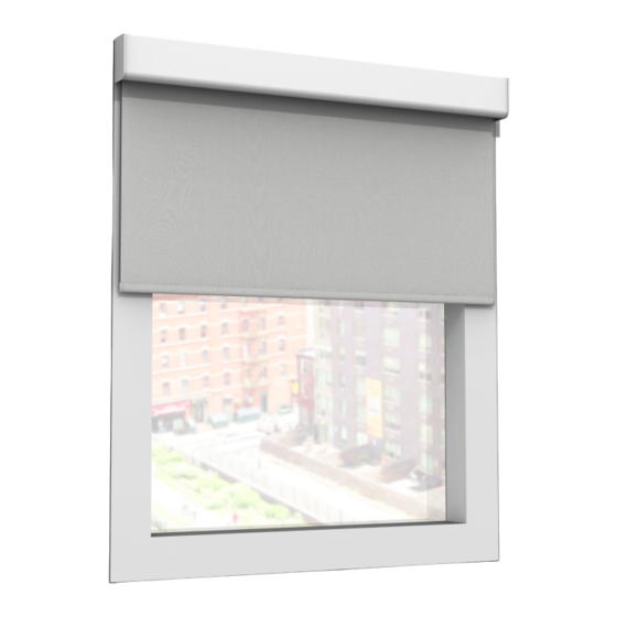
CS-SHADE-ROLLER-BATT
Shade Motor and Hardware for CS-SHADE-ROLLER-BATT with CSA-DECOR3 Brackets
The Crestron® CS-SHADE-ROLLER-BATT with CSA-DECOR3-BRKT
shade mounting brackets allow Crestron shades to be mounted on a wall,
ceiling, pocket, or window jamb. The adjustable mounting brackets allow
adjustments to the shade installation without removing the mounting
brackets from the wall.
Shade Mounting
The CSA-DECOR3-BRKT Series shade brackets are mounted to the wall
or window jamb using the two supplied brackets. The end caps (optional)
and roller shade assembly then attach to the brackets.
CAUTIONS:
There is risk of personal injury and equipment damage if the shade or
l
associated parts fall during mounting. Use care when mounting. Use
proper mounting hardware for the mounting surface (for example,
screws or bolts) when securing the brackets to the surface.
Two or more people are required to properly mount the shades. Three
l
or more people are required to properly mount large shades and
medium-sized coupled shades.
NOTES:
The screws provided with the mounting brackets are intended for use
l
on walls (or jambs) with wood or metal blocking. These screws should
not be used for hollow drywall or masonry installations. It is the
responsibility of the installer to make sure that the mounting method
used is secure.
Ensure that all mounting brackets are level and on the same plane.
l
All shades must be aligned along a single axis (no off-angle
l
positioning).
Mount the Brackets
1. Check for a proper fit by holding the roller shade assembly in the
approximate mounting location. If using a fascia, use the fascia to
measure the proper distance between mounting brackets. The
brackets should be mounted flush with the end of the fascia.
2. Mark the locations of the brackets and make sure that the mounting
points are level and on the same plane. Use a laser level or snap a chalk
line to mark the locations of the brackets. The brackets should be
spaced according to the specifications on the order form.
NOTE:
End caps are used only when the shade is outside mounted
and fascia is used. If inside mounted, end caps are not required unless
the shade brackets protrude from the window opening. Adding end
caps for an inside mount increases the light gap.
3. If using end caps, attach them to the mounting brackets according to
their stamped directions. The end caps snap into place.
Quick Start
1
Advertisement
Table of Contents

Related Manuals for Crestron CS-SHADE-ROLLER-BATT


Summary of Contents for Crestron CS-SHADE-ROLLER-BATT
- Page 1 Mount the Brackets The Crestron® CS-SHADE-ROLLER-BATT with CSA-DECOR3-BRKT shade mounting brackets allow Crestron shades to be mounted on a wall, 1. Check for a proper fit by holding the roller shade assembly in the ceiling, pocket, or window jamb. The adjustable mounting brackets allow approximate mounting location.
- Page 2 Quick Start CS-SHADE-ROLLER-BATT Shade Motor and Hardware for CS-SHADE-ROLLER-BATT with CSA-DECOR3 Brackets 4. Mount the brackets to the outside of the window frame (outside Outside Mount mount) or the inside of the window frame (inside mount). Use hardware that is appropriate for the mounting surface. Make sure the brackets are level and mounted to a flat surface.
- Page 3 Quick Start CS-SHADE-ROLLER-BATT Shade Motor and Hardware for CS-SHADE-ROLLER-BATT with CSA-DECOR3 Brackets Mount the Roller Shade Assembly 4. Push the tab on the motor assembly into the hole in the motor bracket. When the shade is properly seated, the two clips spring down to secure the motor to the bracket.
- Page 4 Quick Start CS-SHADE-ROLLER-BATT Shade Motor and Hardware for CS-SHADE-ROLLER-BATT with CSA-DECOR3 Brackets Adjust the Roller Shade Assembly Make sure that no obstructions exist near the window area that the shade could bump into while traveling (for example, latches and Once the roller shade assembly is mounted, make adjustments to level the cranks).
- Page 5 Quick Start CS-SHADE-ROLLER-BATT Shade Motor and Hardware for CS-SHADE-ROLLER-BATT with CSA-DECOR3 Brackets Swap the Idler and Motor Ends Rotate the keyhole The roller shade assembly can be mounted so that the idler and motor 1. Using a Phillips screwdriver, remove the four screws holding the idler ends are located in the ends of the tube opposite where they were when mount in the left-hand bracket and then remove the idler mount.
- Page 6 Quick Start CS-SHADE-ROLLER-BATT Shade Motor and Hardware for CS-SHADE-ROLLER-BATT with CSA-DECOR3 Brackets Rotate Keyhole: Right-Side Wall Mount to Ceiling Mount Rotate Keyhole: Right-Side Wall Mount to Left Side Wall Mount...
-
Page 7: Battery Pack
Quick Start CS-SHADE-ROLLER-BATT Shade Motor and Hardware for CS-SHADE-ROLLER-BATT with CSA-DECOR3 Brackets Swap the Roller Shade Idler and Motor 4. Replace the positive end of the battery pack. To replace, twist the cap clockwise. If the idler and motor brackets have been swapped, remove the motor 5. - Page 8 Quick Start CS-SHADE-ROLLER-BATT Shade Motor and Hardware for CS-SHADE-ROLLER-BATT with CSA-DECOR3 Brackets 1. Secure the mounting bracket to the wall or window jamb using 2. The mounting bracket has two clips that hold the battery pack in place. appropriate mounting hardware (not supplied). The motor side of the Slide the battery pack onto the clips until it clicks into place.
- Page 9 Quick Start CS-SHADE-ROLLER-BATT Shade Motor and Hardware for CS-SHADE-ROLLER-BATT with CSA-DECOR3 Brackets 4. Replace the positive end of the battery pack. To replace, twist the cap clockwise. 5. Connect the battery-pack cable to the motor. Replace the Batteries Use 8 D-cell batteries (1.5 V alkaline) to power the shade motor. The batteries must be new.
-
Page 10: Controls And Indicators
Quick Start CS-SHADE-ROLLER-BATT Shade Motor and Hardware for CS-SHADE-ROLLER-BATT with CSA-DECOR3 Brackets Test the Shade Before the shade is operated, test the motor to ensure that the shade Motor Programming travels in the correct direction when being operated. The Crestron® digital CSM(I)-QMTDC shade motors are programmed... - Page 11 Failure to follow limits are erased. these instructions may result in damage to the edge of the fabric, which For Crestron Horizontal Sheers, the lower limit is defined as the point is not covered by the warranty. before the hem bar tilts.
- Page 12 Joining a Wireless Network (Wireless Motors Only) Leaving a Wireless Network To leave a wireless network, put the device into Acquire mode, as The device connects to the Crestron network using the SG wireless described in Joining the Wireless Network when no gateway is in Acquire communications protocol.
-
Page 13: Led Diagnostics
Quick Start CS-SHADE-ROLLER-BATT Shade Motor and Hardware for CS-SHADE-ROLLER-BATT with CSA-DECOR3 Brackets LED Diagnostics Error State Crestron CSM(I)-QMTDC motors display error codes using the red LED The LED flashes to provide a visual reference that the motor is operating on the interface. The LED flashes a pattern to indicate the error. -
Page 14: Troubleshooting
Crestron dealers, CSPs, and end-users under a separate End-User License all of the LEDs power supply and motor. Agreement. Both of these Agreements can be found on the Crestron website at are off. www.crestron.com/legal/software_license_agreement. The power connection is... - Page 15 (e.i.r.p.) is not more than that necessary for successful NOTE: Mechanical parts are selected using the Crestron CDT communication. application. A list of parts are also available on the Crestron Industrie Canada (IC) Déclaration de conformité website at www.crestron.com.
- Page 16 Crestron disclaims any proprietary interest in the marks and names referenced FCC authorization. Accordingly, if any user modifications of others. Crestron is not responsible for errors in typography or CAUTION: Changes or modifications not expressly approved by the are sought to be made to the device software or configuration, the photography.
Need help?
Do you have a question about the CS-SHADE-ROLLER-BATT and is the answer not in the manual?
Questions and answers