Advertisement
Quick Links
CSM-QMTDC
Digital QMT
Shade Motor
®
Programming Guide
Description
The Crestron
digital QMT
CSM-QMTDC shade motors are programmed locally using the
®
®
buttons on the motor. The information in this guide serves as a detailed overview of the
programming of the Crestron CSM-QMTDC shade motors.
NOTE: The procedures described in this document can also be performed remotely via
a Crestron control system. The timeout and LED indicators are the same as described in
this document.
Additional Resources
Visit the product page on the Crestron website (www.crestron.com)
for additional information and the latest rmware updates.
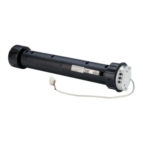
Controls and Indicators
The Crestron CSM-QMTDC shade motors have labeled UP, SET, and DN push buttons
that are used to program the shade. The motors have a multicolor LED that lights red,
amber, green, blue, or white to provide con rmation, operating mode, and error state
feedback. The UP button is located closest to the LED, the SET button is the second
button from the LED, and the DN (down) button is the third button from the LED. Refer to
the illustration below for details.
Crestron CSM-QMTDC Motor Multicolor LED and Push Button Orientation
DN Push Button
SET Push Button
UP Push Button
Multicolor LED
Test the Shade
Before the shade is operated, the motor must be tested to ensure that the motor direction
is correct and that the shade travels correctly while raising and lowering.
WARNING: Care has been taken to ensure that your shade is properly balanced. Prior
to initial operation, please con rm that your brackets have been adjusted so that the
shade hangs level and plumb. Upon startup, run the shade all the way down and check
for plumb. Observe the shade closely as it rolls up. If the shade begins to telescope,
stop immediately and take the appropriate action to ensure the shade tracks properly.
To prevent damage to the fabric from telescoping, you should not leave the shade
unattended during the rst few cycles of operation. Failure to follow these instructions
may result in damage to the edge of the fabric, which is not covered by the warranty.
Test Motor Direction
Press the DN (down) button to lower the shade. If the shade begins to travel up, the motor
direction must be reversed.
To reverse the shade direction, press and hold the SET button for 10 seconds. The red
LED lights for 3 seconds.
NOTE: Reversing the direction of the motor resets any limits that have been previously
set. After setting either the upper or lower limit, the motor automatically enters Limit Setup
mode for the opposite limit. Follow the procedure in "Set Shade Limits" to reassign limits.
Test Shade Travel
Using the DN and UP buttons, ensure that the shade travels to the anticipated lower limit
and then back to the expected upper limit. The shade should not come in contact with any
building materials.
The shade should travel the full length of the window opening and stop before reaching
the top or bottom of the window opening. If the shade does not travel as expected, refer
to "Set Up the Shade" below.
Set Up the Shade
Test Shade Limits
Shade limits are set from the factory, but it may be necessary to reset them depending on
the installation conditions. Test the lower limits by lowering the shade until it reaches its
lower limit. Test the upper limits by raising the shade until it reaches its upper limit. Refer
to "Set Shade Limits" if the limits need to change.
Set Shade Limits
When the shade limits are not set, the red LED blinks three times, pauses for 1 second,
blinks once, pauses for 5 seconds, and then repeats this code until the limits are set.
NOTE: After 8 seconds of inactivity, Limit Setup mode is exited.
Set the lower limit for the shade.
1. Press and hold SET for 4 seconds to enter Limit Setup mode. The LED alternates
between amber and green.
2. Press and release the DN button to begin lower limit setup. The green LED blinks.
3. Use the UP and DN buttons to set the shade to its desired position.
4. Press and hold SET for 4 seconds. The LED turns solid red to con rm that the lower
limit was successfully set.
NOTE: If the upper limit is not set when the lower limit is saved, the motor automatically
enters upper limit mode upon saving the lower limit. This typically occurs when the
motor direction has been reversed and both limits are erased.
Set the upper limit for the shade.
1. Press and hold SET for 4 seconds to enter Limit Setup mode. The LED alternates
between amber and green.
2. Press and release the UP button to begin upper limit setup. The amber LED blinks.
3. Use the UP and DN buttons to set the shade to its desired position.
4. Press and hold SET for 4 seconds. The LED turns solid red to confirm that the upper
limit was successfully set.
NOTE: If the lower limit is not set when the upper limit is saved, the motor switches to
allow setting the lower limit after saving the upper limit. This typically occurs when the
motor direction has been reversed and both limits are erased.
Joining an in NET EX Network (in NET EX Interfaces Only)
The device connects to the Crestron network via the in NET EX
protocol. Use the procedures outlined below to join or leave an in NET EX network and to
verify communications between the device and the control system.
Joining an in NET EX Network
Before a device can be used in a shading system, it must rst join an in NET EX network
by being acquired by an in NET EX gateway.
NOTE: A device can be acquired by only one gateway.
1. Put the in NET EX gateway into Acquire mode from the unit itself or from Crestron
Toolbox™, as described in its manual at www.crestron.com/manuals.
NOTE: In an environment where multiple gateways are installed, only one
gateway should be in the Acquire mode at any time.
2. Place the device into Acquire mode.
a. Tap the SET button three times, then press and hold it down
(tap-tap-tap-press+hold) until the white LED starts to blink (this can take up to 10
seconds).
b. When the white LED blinks, release the button to start the acquire process.
• The interface is acquired when the LED stops blinking.
• If the acquire process fails, the LED blinks rapidly until a button is pressed.
3. Once all devices have been acquired, take the gateway out of Acquire mode. Refer
to the gateways' operations guide for more information
To leave an in NET EX network, put the device into Acquire mode, as described in
"Joining an in NET EX Network" above, when no gateway is in Acquire mode.
Verifying Communications Status
To check the communications status of the device, tap the SET button three times and
then press and hold it down (tap-tap-tap-press+hold) for up to 2 seconds. The LED blinks
to indicate the communications status. Refer to the following table for details.
LED
Turns on for 5 seconds
Device is communicating with the control system.
Blinks three times
Device is communicating with the gateway but the
gateway is not communicating with the control system.
Blinks twice
Device was previously joined to the network but is not
communicating with the gateway.
Blinks once
Device is not joined to the network.
in NET EX Motor Comunication
Refer to the Best Practices for Installation and Setup of Crestron RF Products Reference
Guide (Doc. 6689) at www.crestron.com/manuals if communication issues exist with
recessed or pocket mount installations.
®
communications
COMMUNICATIONS STATUS
Advertisement

Related Manuals for Crestron QMT CSM-QMTDC Series


Summary of Contents for Crestron QMT CSM-QMTDC Series
- Page 1 NOTE: A device can be acquired by only one gateway. Multicolor LED 1. Put the in NET EX gateway into Acquire mode from the unit itself or from Crestron Toolbox™, as described in its manual at www.crestron.com/manuals. NOTE: In an environment where multiple gateways are installed, only one gateway should be in the Acquire mode at any time.
- Page 2 The speci c patents that cover Crestron products are listed at patents.crestron.com. l'établissement d'une communication satisfaisante. Crestron, the Crestron logo, Cresnet, Crestron Toolbox, in NET EX, and QMT are either trademarks or To satisfy RF exposure requirements, this device and its antenna must operate with a separation distance registered trademarks of Crestron Electronics, Inc.
Need help?
Do you have a question about the QMT CSM-QMTDC Series and is the answer not in the manual?
Questions and answers