Advertisement
Quick Links
CSM-QMTDC
Digital QMT
Shade Motor
®
Programming Guide
Description
The Crestron
®
digital CSM-QMTDC shade motors are programmed locally using the
buttons on the motor. The information in this guide serves as a detailed programming
overview of the Crestron CSM-QMTDC shade motors.
NOTE: The procedures described in this document can also be performed remotely
using a control system. The timeout and LED indicators are the same as described in
this document.
Additional Resources
Visit the product page on the Crestron website (www.crestron.com)
for additional information and the latest firmware updates. Use a QR
reader application on your mobile device to scan the QR image.
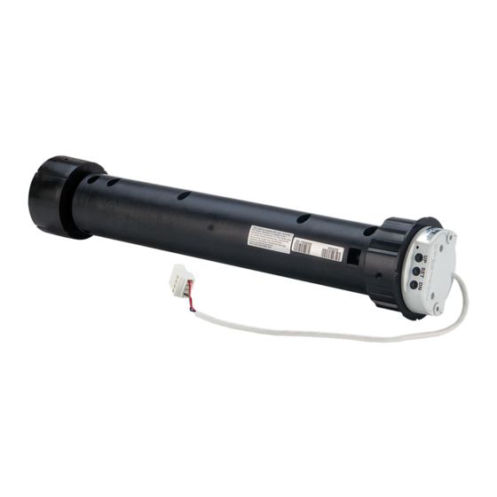
Controls and Indicators
The Crestron CSM-QMTDC shade motors have UP, SET, and DN (down) push buttons
that are used to program the shade. The shade motors have a multicolor LED that lights
red, amber, green, blue, or white to provide confirmation, operating mode, and error state
feedback. The UP button is located closest to the LED, the SET button is the second
button from the LED, and the DN button is the third button from the LED.
Crestron CSM-QMTDC Motor Multicolor LED and Push Button Orientation
DN Push Button
SET Push Button
UP Push Button
Multicolor LED
Test the Shade
Before the shade is operated, test the motor to ensure that the shade travels in the correct
direction when being operated.
NOTE: Before using the CSM-QMTDC shade motor, ensure the device is using
the latest firmware. Check for the latest firmware for the CSM-QMTDC shade motor
at www.crestron.com/firmware. Firmware is loaded onto the device using Crestron
Toolbox™ software.
Test the Motor Direction
Press the DN button to lower the shade about 1 inch. If the shade travels up, reverse the
motor direction.
NOTE: Reversing the motor direction resets all previously set limits. After either the
upper or lower limit is set, the motor automatically enters Limit Setup mode for the
opposite limit. Follow the procedure in "Set the Shade Limits" to reassign limits.
To reverse the shade direction, press and hold the SET button for 10 seconds. The red
LED lights for 3 seconds.
Test the Shade Travel
Test the travel of the shade fabric to ensure that it does not come in contact with building
materials and that the upper and lower shade limits are properly set.
WARNING: Care has been taken to ensure that the shade is properly balanced.
Prior to initial operation, confirm that the brackets are adjusted so that the shade
hangs level and plumb. Upon startup, run the shade all the way down and check for
plumb. Observe the shade closely as it rolls up. If the shade begins to telescope, stop
immediately and take the appropriate action to ensure the shade tracks properly. To
prevent damage to the fabric from telescoping, do not leave the shade unattended
during the first few cycles of operation. Failure to follow these instructions may result in
damage to the edge of the fabric, which is not covered by the warranty.
NOTE: For Crestron Horizontal Sheers, the lower limit is defined as the point before
the hem bar tilts.
Using the DN button, lower the shade until it reaches its lower limit. Verify that the shade
does not come in contact with any building materials. Stop and adjust the mounting
brackets if the fabric contacts any building materials. Verify that the shade stops at the
desired lower limit.
Using the UP button, raise the shade until it reaches its upper limit. Verify that the shade
does not come in contact with any building materials. Stop and adjust the mounting
brackets if the fabric contacts any building materials. Verify that the shade stops at the
desired upper limit. Refer to "Set the Shade Limits" if the shade does not travel to its
upper or lower limit.
Set the Shade Limits
If necessary, set the lower and upper shade limits. If the shade limits are not set, the red
LED flashes three times, pauses for 1 second, flashes once, pauses for 5 seconds, and
then repeats this code until the limits are set.
NOTE: Limit Setup mode exits after 8 seconds of inactivity.
NOTE: If a limit is not set after the upper or lower limit is saved, the motor
automatically enters Limit Setup mode for the opposite limit. This typically occurs after
the motor direction has been reversed and both limits are erased.
NOTE: For Crestron Horizontal Sheers, the lower limit is defined as the point before
the hem bar tilts.
Set the lower limit for the shade.
1. Press and hold the SET button for 4 seconds to enter Limit Setup mode. The LED
alternates between amber and green.
2. Press and release the DN button to begin lower limit setup. The green LED flashes.
3. Use the UP and DN buttons to set the shade to its desired position.
4. Press and hold SET for 4 seconds. The LED turns solid red to confirm that the lower
limit was successfully set.
Set the upper limit for the shade.
1. Press and hold SET for 4 seconds to enter Limit Setup mode. The LED alternates
between amber and green.
2. Press and release the UP button to begin upper limit setup. The amber LED flashes.
3. Use the UP and DN buttons to set the shade to its desired position.
4. Press and hold SET for 4 seconds. The LED turns solid red to confirm that the upper
limit was successfully set.
Joining an infiNET EX
Network (infiNET EX Interfaces Only)
®
The device connects to the Crestron network via the infiNET EX communications protocol.
Use the procedures outlined below to join or leave an infiNET EX network and to verify
communications between the device and the control system.
Joining an infiNET EX Network
Before a device can be used in a lighting system, it must first join an infiNET EX network
by being acquired by an infiNET EX gateway.
NOTE: A device can be acquired by only one gateway.
1. Put the infiNET EX gateway into Acquire mode from the unit itself or from Crestron
Toolbox, as described in its manual at www.crestron.com/manuals.
NOTE: In an environment where multiple gateways are installed, only one
gateway should be in Acquire mode at any time.
2. Place the device into Acquire mode.
a. Press the SET button three times, and then press and hold it down (tap-tap-tap-
press+hold) until the white LED on the device flashes once (this can take up to 10
seconds).
b. Release the button to start the acquire process. The LED flashes slowly to show
that the device is actively scanning the infiNET EX network.
• The LED turns on for 5 seconds to show that the device has been successfully
acquired to the infiNET EX network.
• The LED flashes quickly to indicate that the device was not successfully
acquired by the infiNET EX network. Press the SET button to acknowledge
failure to acquire the infiNET EX network. Ensure the gateway is in Acquire
mode and within range before attempting the acquire process again.
3. Once all devices have been acquired, take the gateway out of Acquire mode. Refer
to the gateway's manual for details.
Leaving an infiNET EX Network
To leave an infiNET EX network, put the device into Acquire mode, as described in
"Joining an infiNET EX Network" above, when no gateway is in Acquire mode.
Verifying Communications Status
To check the communications status of the device, tap the SET button three times and
then press and hold it down (tap-tap-tap-press+hold) for up to 2 seconds. The LED flashes
to indicate the communications status. Refer to the following table for details.
LED
Turns on for 5 seconds
The device is communicating with the control system.
Flashes twice
The device was previously joined to the network but is not
communicating with the gateway.
Flashes once
The device is not joined to the network.
NOTE: Wireless networks composed predominantly of battery-powered devices
may need additional infiNET EX expanders, such as the CLW-EXPEX or GLA-EXPEX
or other non-battery powered infiNET EX devices (all not included), to ensure proper
functionality of the network and battery life for the devices. Refer to the Best Practices
for Installation and Setup of Crestron RF Products (Doc. 6689) for complete system
design guidelines, or contact Crestron True Blue Support for further assistance.
COMMUNICATIONS STATUS
Advertisement

Subscribe to Our Youtube Channel
Related Manuals for Crestron QMT CSM-QMTDC


Summary of Contents for Crestron QMT CSM-QMTDC
- Page 1 EX gateway. NOTE: A device can be acquired by only one gateway. 1. Put the infiNET EX gateway into Acquire mode from the unit itself or from Crestron Toolbox, as described in its manual at www.crestron.com/manuals.
- Page 2 Federal Communications Commission (FCC) Compliance Statement interest in the marks and names of others. Crestron is not responsible for errors in typography or This device complies with part 15 of the FCC Rules. Operation is subject to the following conditions: photography.
Need help?
Do you have a question about the QMT CSM-QMTDC and is the answer not in the manual?
Questions and answers