
Related Manuals for DFI G586VPS Pro


Summary of Contents for DFI G586VPS Pro
- Page 1 All manuals and user guides at all-guides.com G586VPS Pro Rev. B1 + System Board User’s Manual - 31560927 -...
- Page 2 All manuals and user guides at all-guides.com FCC Statement on Class B Notice:...
- Page 3 All manuals and user guides at all-guides.com Table of Contents Chapter 1: Introduction ................5 Chapter 2: Hardware Installation ............10 Chapter 3: Software Installation ............32...
- Page 4 All manuals and user guides at all-guides.com Chapter 4: Troubleshooting Checklist ............60 Appendix A: Memory and I/O Maps ............64 Appendix B: Connector Pin Assignments ..........66...
- Page 5 All manuals and user guides at all-guides.com Chapter 1 Introduction...
- Page 6 All manuals and user guides at all-guides.com Features and Specifications PROCESSOR • SYSTEM CLOCK • CPU Clock PCI Clock ISA Bus Clock SYSTEM CONTROLLER CACHE MEMORY • SYSTEM MEMORY...
- Page 7 All manuals and user guides at all-guides.com BIOS ENERGY EFFICIENT DESIGN PCI IDE INTERFACE INTEGRATED I/O CPU SOCKET • CPU POWER SUPPLY...
- Page 8 All manuals and user guides at all-guides.com CONNECTORS EXPANSION SLOTS PCI MASTER...
- Page 9 All manuals and user guides at all-guides.com Package Checklist...
- Page 10 All manuals and user guides at all-guides.com Chapter 2 Hardware Installation Preparing the Area Handling the System Board...
- Page 11 All manuals and user guides at all-guides.com Static Electricity Precautions Warning: Electrostatic discharge (ESD) can damage your processor, disk drives, add-in boards, and other components. Perform the upgrade instruction procedures described at an ESD workstation only. If such a station is not available, you can provide some ESD protection by wearing an anti- static wrist strap and attaching it to a metal part of the system chassis.
- Page 12 All manuals and user guides at all-guides.com...
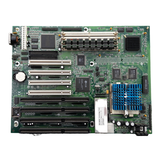
- Page 13 All manuals and user guides at all-guides.com Board Layout...
- Page 14 All manuals and user guides at all-guides.com System Memory SIMMs Memory Size...
- Page 15 All manuals and user guides at all-guides.com Bank 0 Bank 1 SIMM2 SIMM4 Memory Size SIMM1 SIMM3...
- Page 16 All manuals and user guides at all-guides.com Bank 0 Bank 1 SIMM2 SIMM4 Memory Size SIMM1 SIMM3 Installing a SIM Module Pin 1...
- Page 17 All manuals and user guides at all-guides.com Cache Memory Onboard Cache Cacheable Memory Jumper Settings for Cache Memory Jumper JP7 CPU Installation...
- Page 18 All manuals and user guides at all-guides.com JP10A JP13 P-rating System Pins Pins Pins Bus CLK Speed JP10C JP10 Note:...
- Page 19 All manuals and user guides at all-guides.com JP13 CPU Speed System Pins Pins Pins JP10A Bus CLK JP10 JP10C Note: P54C/P55C...
- Page 20 All manuals and user guides at all-guides.com Installing Upgrade CPUs Warning: Open the socket only if you are actually installing a CPU. The warranty on the original CPU will be voided if the S/N seal is broken. Before proceeding with the upgrade, take note of the following. The micropro- cessor and heatsink may be hot if the system has been running.
- Page 21 All manuals and user guides at all-guides.com Lifting the Handle...
- Page 22 All manuals and user guides at all-guides.com Positioning the CPU Above the ZIF Socket...
- Page 23 All manuals and user guides at all-guides.com Clearance Requirements Fan Exhaust...
- Page 24 All manuals and user guides at all-guides.com Jumper Settings for Master IDE Jumper JP14 Jumper Settings for Password Clear Jumper JP16...
- Page 25 All manuals and user guides at all-guides.com Jumper Settings for Display Jumper JP17 Jumper Settings for Internal/External Battery Jumper JP18...
- Page 26 All manuals and user guides at all-guides.com Factory Testing Jumper JP5: JP6: JP10B: JP12:...
- Page 27 All manuals and user guides at all-guides.com Built-in Ports Floppy Cable Printer Cable Serial Ports Mouse Port Cable Serial Ports Port Configuration COM1 COM2 COM3 COM4 Connecting the Serial Ports...
- Page 28 All manuals and user guides at all-guides.com PS/2 Mouse Port Parallel Port Connecting the Parallel Printer Port Floppy Disk Drive Controller...
- Page 29 All manuals and user guides at all-guides.com Connecting the Floppy Disk Cable IDE Hard Disk Interface Note: Only Enhanced IDE hard drives or ATAPI CD-ROMs can be connected to the IDE interface. Connecting the IDE Hard Disk Interface Pin 1...
- Page 30 All manuals and user guides at all-guides.com Note: The IDE cable with a standard 40-pin connector (without the keying mecha- nism) can be installed in the PCI IDE shrouded header. Be extremely care- ful to match the colored edge of the ribbon with pin 1 of the header. Connecting the Hard Disk Cable Note: Refer to your disk drive user’s manual for information about selecting...
- Page 31 All manuals and user guides at all-guides.com Warning: Do not run FDISK and FORMAT programs on a drive that has already been formatted or you will lose all programs and data stored on the drive. Installing Expansion Cards...
- Page 32 All manuals and user guides at all-guides.com Chapter 3 Software Installation Press DEL to enter setup Award BIOS Setup Utility...
- Page 33 All manuals and user guides at all-guides.com ↑↓→← Note: The settings on the BIOS setup screens on the following pages are for reference only. These settings vary according to your system’s configu- ration and should not be referred to as the standard default setting. Standard CMOS Setup ↑↓→←...
- Page 34 All manuals and user guides at all-guides.com Date Time Primary Master, Primary Slave, Secondary Master and Secondary Slave...
- Page 35 All manuals and user guides at all-guides.com Drive A and Drive B Note: Choosing an incorrect type might cause your system to format the floppy disk improperly and you will not be able to access your data.
- Page 36 All manuals and user guides at all-guides.com Video Halt On...
- Page 37 All manuals and user guides at all-guides.com Memory...
- Page 38 All manuals and user guides at all-guides.com BIOS Features Setup ↑↓→← Virus Warning...
- Page 39 All manuals and user guides at all-guides.com CPU Internal Cache and External Cache Quick Power On Self Test...
- Page 40 All manuals and user guides at all-guides.com Boot Sequence Swap Floppy Drive Boot Up Floppy Seek...
- Page 41 All manuals and user guides at all-guides.com Boot Up NumLock Status Boot Up System Speed IDE HDD Block Mode Gate A20 Option...
- Page 42 All manuals and user guides at all-guides.com Memory Parity Check Typematic Rate Setting Typematic Rate (Chars/Sec)
- Page 43 All manuals and user guides at all-guides.com Typematic Delay (Msec) Security Option PCI/VGA Palette Snoop...
- Page 44 All manuals and user guides at all-guides.com OS Select for DRAM > 64MB Video BIOS Shadow C8000-CBFFF Shadow to DC000-DFFFF Shadow...
- Page 45 All manuals and user guides at all-guides.com Chipset Features Setup ↑ ↓ → ←...
- Page 46 All manuals and user guides at all-guides.com Power Management Setup ↑ ↓ → ← Power Management...
- Page 47 All manuals and user guides at all-guides.com PM Control by APM Video Off Method PM Timers...
- Page 48 All manuals and user guides at all-guides.com IRQ1 - IRQ15 PNP/PCI Configuration ↑ ↓ → ←...
- Page 49 All manuals and user guides at all-guides.com Resources Controlled By Load BIOS Defaults Load BIOS Defaults (Y/N)? N Load Setup Defaults...
- Page 50 All manuals and user guides at all-guides.com Load Setup Defaults (Y/N)? N Integrated Peripherals ↑ ↓ → ← Onboard FDC Controller Onboard Serial Port 1 and Onboard Serial Port 2...
- Page 51 All manuals and user guides at all-guides.com Onboard Parallel Port Infrared Duplex Type Note: The G586VPS Pro only supports IrDA that is an HP standard.
- Page 52 All manuals and user guides at all-guides.com Onboard IDE Controller Supervisor Password Enter Password: Confirm Password:...
- Page 53 All manuals and user guides at all-guides.com User Password IDE HDD Auto Detection...
- Page 54 All manuals and user guides at all-guides.com Hard Drive Mode...
- Page 55 All manuals and user guides at all-guides.com...
- Page 56 All manuals and user guides at all-guides.com Note: To support LBA or Large mode, address translation software is included in the Award BIOS HDD Sevice Routine (INT13h). If you are running an operating system that bypasses the BIOS INT13 Service Routine, LBA and Large Mode may fail.
- Page 57 All manuals and user guides at all-guides.com Save & Exit Setup Save to CMOS and Exit (Y/N)? N Reboot System (Y/N)? N Exit Without Saving Quit Without Saving (Y/N)? N...
- Page 58 All manuals and user guides at all-guides.com System Error Report POST Beep Error Messages CMOS BATTERY HAS FAILED CMOS CHECKSUM ERROR DISPLAY SWITCH IS SET INCORRECTLY...
- Page 59 All manuals and user guides at all-guides.com FLOPPY DISK(S) fail (80) → Unable to reset floppy subsystem. FLOPPY DISK(S) fail (40) → Floppy type mismatch. Hard Disk(s) fail (80) → HDD reset failed. Hard Disk(s) fail (40) → HDD controller diagnostics failed. Hard Disk(s) fail (20) →...
- Page 60 All manuals and user guides at all-guides.com Chapter 4 Troubleshooting Checklist Monitor/Display...
- Page 61 All manuals and user guides at all-guides.com Power Supply Floppy Drive...
- Page 62 All manuals and user guides at all-guides.com Hard Drive Parallel Port Serial Port...
- Page 63 All manuals and user guides at all-guides.com Keyboard System Board...
- Page 64 All manuals and user guides at all-guides.com Appendix A Memory and I/O Maps Memory Address Map Address Name Function...
- Page 65 All manuals and user guides at all-guides.com I/O Address Map I/O Address Function Note: The I/O address hex 0000 to 00FF are reserved for the system board I/O. Hex 0100 to 03FF are available on the I/O channels.
- Page 66 All manuals and user guides at all-guides.com Appendix B Connector Pin Assignments Connector J1 Connector J6 Function Function Connector J2 Connector J16 Function Function Connector J3 Connector J17 Function Function...
- Page 67 All manuals and user guides at all-guides.com Connector J4 Function Connector J5 Function...
Need help?
Do you have a question about the G586VPS Pro and is the answer not in the manual?
Questions and answers