
Related Manuals for Afore On-Grid


Summary of Contents for Afore On-Grid
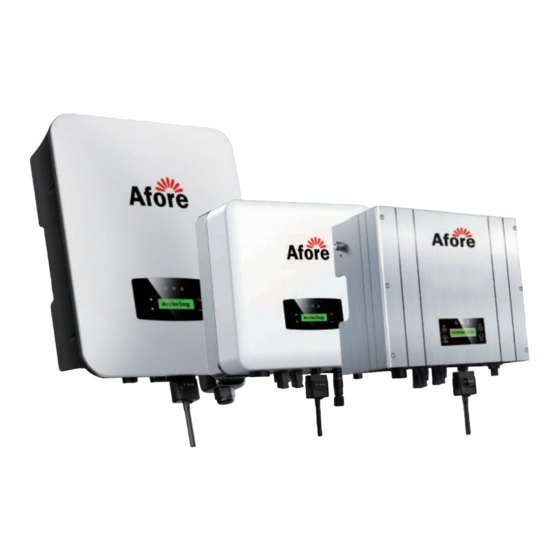
- Page 1 On-Grid PV Inverter Installation and Operation Manual Building 7, No.333 Wanfang Rd, Minhang District, Shanghai, China. 201112...
-
Page 2: Table Of Contents
3.3 Mounting Location ......3.4 Installation On-grid PV Inverter ..... . -
Page 3: About This Manual
About This Manual 1.About This Manual 1.1 Scope of Validity This manual describes the installation, commissioning, operation and maintenance of the following on-grid PV inverters produced by Afore New Energy: Single-Phase (One MPPT Tracker) HNS3600TL-1 Single-Phase (Two MPPT Trackers) HNS3000TL... - Page 4 About This Manual Single-Phase (HNS3000TL / HNS3600TL / HNS4000TL / HNS5000TL6 / HNS3600TL-1): Portal web Porta Smart-phone Cloud server DCA+ Circuit Breaker DCA- Circuit Breaker 1 Surge Protective PV Array Device Surge Protective AC Grid Device DCB+ DCB- Circuit Breaker 1 Surge Protective PV Array Device...
- Page 5 Safety & Symbols Single-Phase (HNS9000TL / HNS10000TL): Portal web Porta Smart-phone Cloud server PVA1 DCA1+ DCA1- Surge Protective PV Array Circuit Breaker 1 Device PVA2 DCA2+ Circuit Breaker DCA2- PV Array Circuit Breaker 1 Surge Protective Device PVB1 Surge Protective AC Grid DCB1+ Device...
-
Page 6: Safety & Symbols
6. Please ensure that the used device and any relevant accessories are disposed of in accordance with applicable regulations. 7. Afore inverter should be placed upwards and handled with care in delivery. Pay attention to waterproof. 8.Alternative uses, modifications to the inverter not recommended by Afore or the installation of components not sold by Afore New Energy void the warranty claims. -
Page 7: Explanations Of Symbols
100A HNS10000TL 2.2 Explanations of Symbols Afore inverter strictly comply with relevant safety standards. Please read and follow all the instructions and cautions during installation, operation and maintenance. Danger of electric shock The inverter contains fatal DC and AC power. All work on the inverter must be carried out by qualified personnel only. -
Page 8: Installation
Installation 3.Installation 3.1 Package Unpacking On receiving the inverter, please check to make sure the packing and all of the components are not missing or damaged. Please contact your dealer directly for supports if there is any damage or missing components. Package List Open the package, please check the packing list shown as below. - Page 9 Installation Single-Phase (HNS3000TL / HNS3600TL / HNS4000TL / HNS5000TL6 / HNS3600TL-1): Certificate Quick Warranty Installation Card Inspection Instructions Monitor User Manual Items No. Qty Items Solar Inverter Plastic Expansion Tube Certificate Of Inspection Mounting Bracket Screw Quick Installation Instructions Security Screw Warranty Card DC Connector sets Wall Mounting bracket...
- Page 10 Installation Single-Phase (HNS6000TL / HNS7000TL / HNS8000TL / HNS9000TL / HNS10000TL): Monitor Quick Certificate Warranty User Installation Card Manual Instructions Inspection 5 14 5 15 No. Qty Items No. Qty Items Solar Inverter Mounting Bracket Screw Certificate Of Inspection Plastic Expansion Tube Quick Installation Instructions Security Screw Warranty Card...
-
Page 11: Product Overview
Installation 3.2 Product Overview Single-Phase (HSN5000TL): 345 mm 170 mm Single-Phase (HNS3000TL / HNS3600TL / HNS4000TL / HNS5000TL6 / HNS3600TL-1): 360 mm 142 mm... - Page 12 Installation Single-Phase (HNS6000TL / HNS7000TL / HNS8000TL): 370mm 192mm Single-Phase (HNS9000TL / HNS10000TL): 370mm 192mm Overview of the Connection Area The following figures show the assignment of the individual connection areas on the bottom of the inverter.
- Page 13 Installation Single-Phase (HNS5000TL): Single-Phase (HNS3000TL / HNS3600TL / HNS4000TL / HNS5000TL6 / HNS3600TL-1):...
- Page 14 Installation Single-Phase (HNS6000TL / HNS7000TL / HNS8000TL): Single-Phase (HNS9000TL / HNS10000TL): PV Inverter Items DC Connectors ( + ) For PV String DC Connectors ( − ) For PV String AC Connector Monitor Module Port RJ45 Port (DRM)
-
Page 15: Mounting Location
Installation 3.3 Mounting Location The inverters are designed for indoor and outdoor installation (IP65), to increase the safety, performance and lifespan of the inverter, please select the mounting location carefully based on the following rules: The inverter should be installed on a solid surface, far from flammable or corrosion materials, where is suitable for inverter’s weight and dimensions. -
Page 16: Installation On-Grid Pv Inverter
Installation Leave the enough space around inverter, easy for accessing to the inverter, connection points and maintenance. 300mm 100mm 100mm 500mm 3.4 Installation On-grid PV Inverter Step 1 Single-Phase (HNS5000TL): 241.5mm 26mm 35mm 26mm 328.5mm Single-Phase (HNS3000TL / HNS3600TL / HNS4000TL /... - Page 17 Installation Single-Phase (HNS6000TL / HNS7000TL / HNS8000TL / HNS9000TL / HNS10000TL): 219mm 17mm 264mm Step 2 Single-Phase (HNS5000TL): Single-Phase (HNS3000TL / HNS3600TL / HNS4000TL / HNS5000TL6 / HNS3600TL-1):...
- Page 18 Installation Single-Phase (HNS6000TL / HNS7000TL / HNS8000TL / HNS9000TL / HNS10000TL): Step 3 Single-Phase (HNS5000TL): Security screw Single-Phase (HNS3000TL / HNS3600TL / HNS4000TL / HNS5000TL6 / HNS3600TL-1): Security screw...
-
Page 19: Electrical Connection
Installation Single-Phase (HNS6000TL / HNS7000TL / HNS8000TL / HNS9000TL / HNS10000TL): Security screw 3.5 Electrical Connection 3.5.1 PV Connection The inverter have one or two-MPPT channels, can be connected with one or two strings of PV panels. Please make sure below requirements are followed before connecting PV panels / strings to the inverter. - Page 20 Installation Step 2 Positive Crimp Contact Negative Crimp Contact Note: Please use PV connector crimper to pinch the point of the arrow. Step 3 HNS3000TL / HNS3600TL / HNS5000TL HNS4000TL / HNS5000TL6 / HNS3600TL-1 WIFI WIFI HNS6000 / HNS7000 / HNS8000TL HNS9000 / HNS10000TL Note: You’ll hear click sound when the connector assembly is correct.
-
Page 21: Grid Connection
Installation 3.5.2 Grid Connection The on-grid PV inverters work with grid (220/230/240 Vac, 50/60 Hz). The external AC switch should be installed between inverter and grid to isolate from grid. Please make sure below requirements are followed before connecting AC cable to the inverter. - Page 22 Installation Step 3 Connect AC line, Live line (L), Neutral line (N) and Ground Wire (PE) according to polarity. Step 4 HNS5000TL HNS3000TL / HNS3600TL / HNS4000TL / HNS5000TL6 / HNS3600TL-1 Connect AC terminals and waterproof head, tighten the cap, make sure they clip closely together.
- Page 23 Installation Single-Phase (HNS6000TL / HNS7000TL / HNS8000TL / HNS9000TL / HNS10000TL): Step 1 Cable suggestion: 6-8kW Cross-section (Copper) 4-6mm² / 10AWG 9-10kW Cross-section (Copper) 6-10mm² / 8AWG After the terminals are crimpped, wrap the joint position with insulation tape. 10±0.5mm Note: The wiring terminals should be wrapped with insulation tape, otherwise it will cause a short circuit and damage the inverter.
- Page 24 Installation HNS9000 / HNS10000TL WIFI Step 3 WIFI Fix junction box with 4 wiring cover screws...
-
Page 25: Earth (Grounding) Connection
Installation 3.5.3 Earth (Grounding) Connection Note: The user must connect a protective earth (PE) terminal to prevent electric shock. And make sure this PE terminal is properly grounded. Step 1 Grounding terminal 3~5 mm Note: Earth cable PE suggestion: Cross-section (Copper) 6mm² Step 2 Single-Phase (HNS5000TL): Grounding terminal is connected to the inverter at left or right side... - Page 26 Installation Single-Phase (HNS3000TL / HNS3600TL / HNS4000TL / HNS5000TL6 / HNS3600TL-1): Single-Phase (HNS6000TL / HNS7000TL / HNS8000TL / HNS9000TL / HNS10000TL): Earth Fault Alarm The HNS series inverter is equipped with an earth fault alarm. When earth fault occurs, the fault indicator at the front LED screen will light up. And the buzzer of the inverter will keep ringing until the fault is resolved.
-
Page 27: Communication Connection (Wifi / Ethernet / Gprs / Rs485)
Installation 3.5.4 Communication Connection The monitoring module could transmit the data to the cloud server, and display the data on the PC, tablet and smart-phone. Install the WIFI / Ethernet / GPRS / RS485 Communication WIFI / Ethernet / GPRS / RS485 communication is applicable to the inverter. Please refer to "WIFI&Ethernet&GPRS Connection Manual"... - Page 28 Installation Step 2 Fasten Fasten HNS3000TL / HNS3600TL / HNS5000TL HNS4000TL / HNS5000TL6 / HNS3600TL-1 WIFI WIFI Fasten Fasten HNS6000 / HNS7000 / HNS8000TL HNS9000 / HNS10000TL...
- Page 29 Installation DRM response modes DRM is provided to support several response modes by giving control signals. Prepare RJ45 connector and a communication cable. Assemble the RJ45 connector, Pins are defined as follow. DRED DRED DRED...
- Page 30 Installation DRED connection circuit RJ45 socket pin assignment Pin Assignments Front View 12345678 → RJ45 Socket RJ45 Plug Assignment Assignment DRM 1/5 RefGen DRM 2/6 COM/DRM0 DRM 3/7 RS485 A ( 24 ) DRM 4/8 RS485 B ( 25 )
-
Page 31: Operation
Operation 4. Operation 4.1 Control Panel POWER GRID FAULT DOWN N o. Items N o. Items LCD Display ENT Touch Button UP Touch Button POWER LED Indicator DOWN Touch Button GRID LED Indicator ESC Touch Button FAULT LED Indicator Sign Power Color Explanation... -
Page 32: Menu Structure
Operation 4.2 Menu Structure Second Level Menu HNS5000TL Version:M Vxxx First Level Menu Inverter Info Version:S Vxxx Version:C Vxxx S/N(Machine)S6xxxxxxxx S/N(Wifi)xxxxxx Wifi Info IP(Wifi)192.168.xx.xx Error Record No Error Date: 2020-Dd-Mm Date&Time Time: Hh:Mm:Ss Three Level Menu Safety PassWord xxxx Output P% PassWord xxxx Freq Range PassWord xxxx... -
Page 33: Setting
Safety Set the information of the country/region code Q(Var)Mode Power quality response Function Enable Function use and closure 4.3 Setting 4.3.1 Startup Setting Afore New Energy Normal 1s Delay Power=xx W Date&Time UP/DOWN Adjust Date&Time UP/DOWN Select Press ENT to confirm Date&Time... - Page 34 Operation UP/DOWN UP/DOWN Select Function Enable Password: 5432 Function Enable PassWord Safety xxxx UP/DOWN Select Upstream:OFF Upstream:OFF GroundLine:ON GroundLine:OFF UP/DOWN Select Press ENT to confirm DRM:ON Note: If GroundLine is not turned on, it cannot detect whether the machine is grounded. After GroundLine and DRM functions are turned on, the power must be cut off before normal use.
-
Page 35: Power Quality Response Mode Setting
Operation 4.3.4 Power Quality Response Mode Setting 4.3.4.1 Enable Power Quality Response Modes Power Quality Response Modes can be enabled via the LCD menu. Refer to section 4.3.4.1 (a)~(d) of this manual. a. Active Power Control Power Factor UP/DOWN Select Setting Normal Setting Power=xxW... - Page 36 Operation b. Voltage Control Reactive Power UUP/DOWN Select Setting Normal Setting Power=xxW PtoGrid UP/DOWN UP/DOWN Select Password: 6231 Q (Var) Mode Q(Var)Mode PassWord 10min OVR xxxx UP/DOWN Set grid voltage percentage UP/DOWN Select 2 Press ENT to confirm PQ Set X1: 90 X2: 96 X3: 104 X4: 112 UP/DOWN Set reactive power percentage...
-
Page 37: Active Power Mode Set
Operation c. Fixed Power Factor UP/DOWN Select Setting Normal Setting Power=xxW PtoGrid UP/DOWN Select Q (Var) Mode Q(Var)Mode PassWord 上/下选择 密码:6231 10min OVR xxxx UP/DOWN Set PF value UP/DOWN Select 3 Press ENT to confirm PQ Set 1.00 Note: Set PF (-0.8, +0.8), Default 1,Resolution 0.01. When PQ Set is 3, Power Quality Response Mode is enabled d. -
Page 38: Disable Power Quality Response Modes
Operation 4.3.4.2 Disable Power Quality Response Modes Power Quality Response Modes can be disabled via the LCD menu. Refer to section 4.3.4.2 of this manual. UP/DOWN Select Setting Normal Setting Power=xxW PtoGrid UP/DOWN UP/DOWN Select Password: 6231 Q (Var) Mode Q(Var)Mode PassWord 10min OVR... - Page 39 Operation b. Volt-Watt UP/DOWN Select Inverter Info Normal Inverter Info Power=xxW Wifi Info UP/DOWN UP/DOWN Select HNSxxTL Select Protect UP+ENT Press HNSxxTL at the same time Protect Version:M Vxxx Mainchine Type Press UP/DOWN to select 0, Press the ENT continuously to press ENT to confirm and exit select the 12th digit 1110 0010 0000 0000...
-
Page 40: Frequency Protection Range (Freq Range) Setting
Operation 4.3.5 Frequency protection range (Freq Range) Setting UP/DOWN Select Setting Normal Setting Power=xxW PtoGrid UP/DOWN UP/DOWN Select Freq Range Password: 5432 Freq Range PassWord xxxx Volt Range UP/DOWN UP/DOWN set level 1 frequency upper limit set protection Time FH1= xx Hz FH1= xx Hz Time= xx*20ms Time= xx*20ms... -
Page 41: Voltage Protection Range (Volt Range) Set
Operation 4.3.6 Voltage protection range (Volt Range) set UP/DOWN Select Setting Normal Setting Power=xxW PtoGrid UP/DOWN UP/DOWN Select Volt Range Password: 5432 Volt Range PassWord xxxx Del Err Record UP/DOWN UP/DOWN set level 1 voltage upper limit protection set protection Time VH1= xx V VH1= xx V Time= xx*20ms... -
Page 42: Generation Control Funcion Set
Operation 4.3.8 Generation control funcion set UP/DOWN Select PtoGrid Normal PtoGrid Power=xxW Inverter Info UP/DOWN UP/DOWN Set the value of P1 Password: 5432 P1: xx VA PassWord xxxx P2: xx VA UP/DOWN UP/DOWN Set the value of P2 Set the value of P3 P2: xx VA P3: xx W P3: xx W... - Page 43 Operation Generation control funcion system diagram Afore Simplex Afore Simplex SAPM-10KW Meter A SAPM-10KW Meter B RS485 PV GENERATOR GRID HNS5000TL ..Communication path Power path HOUSEHOLD CONSUMERS Afore Simplex Afore Simplex SAPM-10KW Meter A SAPM-10KW Meter B RS485 PV GENERATOR...
-
Page 44: Active Anti-Islanding Protection
The method of active anti-islanding protection: Shifting the frequency of the inverter away from nominal conditions in the absence of a reference frequency (frequency shift); 4.5 Instructions of view inverter firmware version Afore New Energy Normal 1s Delay Power=xx W... -
Page 45: Shut Down & Restart The Inverter
Shut Down & Restart the Inverter Commissioning Procedures • Turn on the AC switch between inverter output and the public grid; • Turn on the DC switch on the inverter; • Turn on the PV switch of the system. 6. Shut Down & Restart the Inverter 6.1 Shut down •... - Page 46 Maintenance&Trouble Shooting Trouble-Shooting List Error Code Error Message Possible Fault Correctie Measure Display Ground Fault Ground Fault Circuit GFCI Fault restart the inverter Circuit Interrupter Interrupter fault fault · check PV input voltage within Bus High 450Vdc(up to 3.0kw model), Bus Voltage High ·...
-
Page 47: Specifications
Specifications 8. Specifications PV Input Data HNS3600TL-1 HNS3000TL HNS3600TL HNS4000TL HNS5000TL6 HNS5000TL Max. DC Power ( W ) 5400 7000 4500 5400 6000 7000 Max. DC Voltage ( V ) MPPT Voltage Range ( V ) 70-550 70-550 70-550 70-550 70-550 70-550 Min Opera�ng DC Voltage( V ) - Page 48 Specifications PV Input Data HNS6000TL HNS7000TL HNS8000TL HNS9000TL HNS10000TL 8400 9800 11200 12600 14000 Max. DC Power ( W ) Max. DC Voltage ( V ) 70-550 70-550 70-550 70-550 70-550 MPPT Voltage Range ( V ) Min Opera�ng DC Voltage( V ) Start-up Voltage (V) 26+26 Max.
Need help?
Do you have a question about the On-Grid and is the answer not in the manual?
Questions and answers