
Related Manuals for Afore Anybuild BNT KTL Series


Summary of Contents for Afore Anybuild BNT KTL Series
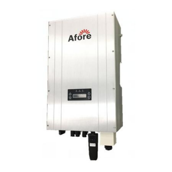
- Page 1 USER’S MANUAL On-Grid PV Inverter Anybuild Series:BNTxxxKTL(xxx=012,013,015) Version 03.610100003002-V0.02 :...
- Page 2 As a customer-oriented company, Afore is always trying to improve herself and enhance customer satisfaction. High quality is the fountain of life for Afore, not just in product quality control, but also in quality of service and support. Afore is able to help customers reduce energy consumption and carbon...
-
Page 3: Table Of Contents
CONTENTS 1 ABOUT THIS MANUAL..................................3 ..................................3 1.1 S COPE OF ALIDITY ....................................4 1.2 T ARGET ROUP ................................4 1.3 A DDITIONAL NFORMATION 2 SAFETY INSTRUCTIONS..................................4 ..................................4 2.1 S AFETY RECAUTIONS ................................5 2.2 E XPLANATIONS OF YMBOLS 3 UNPACKING....................................... -
Page 4: Target Group
8. Packed with damping EPE and carton, Afore inverter should be placed upwards and handled with care in delivery. Pay attention to waterproof. -
Page 5: Explanations Of Symbols
9.Alternative uses, modifications to the inverter not recommended by Afore or the installation of components not sold by Afore New Energy void the warranty claims. 2.2 Explanations of Symbols Symbol Explanation Danger of Electric Shock. The inverter is directly connected with the public grid. All work on the inverter must be carried out by qualified personnel only. -
Page 6: Identifying The Inverter
BNTxxxKTL(xxx=012, 013, 015)assembly parts are as listed below: Object Quantity Description Object Quantity Description Solar inverter Wall mounting bracket User manual Certificate of inspection Installation diagram Notice for installation Warranty card RV5.5-6 terminal Plastic Expansion Tube Tapping screw Security screw Screwdriver for security screw DC plug connector Screw... -
Page 7: Selecting The Appropriate Mounting Location
Do not install the inverter near any inflammable or explosive items. The inverter will be directly connected with high voltage power generation device. The installation must be performed by qualified personnel only in compliance with national or local standards and regulations. CAUTION! Danger of burn injuries due to hot enclosure parts. -
Page 8: Mounting The Inverter With Wall Mounting Bracket
• Vertical installation, wiring area must be downside, lateral installation is not allowed; in backward tilted installation, tilt angle should not exceed 30 degrees; Forward tilted, horizontal or inverted installation is not allowed. 4.3Mounting the Inverter with Wall Mounting Bracket 1. -
Page 9: 5Electrical Connection
2. Fix the wall mounting bracket with the equipped self-tapping screw. 3. Hang the inverter to the mounting bracket and ensure the slot is fitted on the bracket. 4. Check to ensure the inverter is correctly seated. Make sure to lock it with the security screws. (See the figure below.) 5 Electrical Connection... -
Page 10: Overview Of The Connection Area
Notes: 1. Electrical installation & maintenance shall be conducted by licensed electrician and shall comply with local Wiring Rules. 2. After the inverter has been installed in its fixed position, the electrical connection to the unit can be established. 3. Make sure Max. Open Voltage and short-circuit current of the each PV strings accord with the Spec. 4. -
Page 11: Connection To The Public Grid (Ac)
5.2 Connection to the Public Grid (AC) 5.2.1 Conditions for Connection CAUTION! Unit Disconnection From Load Disconnect the circuit breakers and switches of inverters AC and DC sides. 5.2.2 Connection to Public Grid (AC) Measure the grid voltage to make sure within the permissible range. Disconnect the circuit breaker between the inverter and the grid. -
Page 12: Connection To The Pv Generator (Dc)
6. Close junction box and tight the screws 5.3 Connection to the PV Generator (DC) CAUTION! Unit Disconnection From Load Disconnect circuit breakers and switches on both DC and AC sides. 5.3.1 Conditions for the DC Connection • The connected PV modules must meet following requirements –... - Page 13 To assemble the DC plug connectors, proceed as detailed below. Ensure the plug connectors have the correct polarity. The plug connector in DC side includes male and female as blow. Please note that the sizes of metal connecting tubes are different. The bigger one is for female connector and the smaller one is for male connector.
- Page 14 Positive PV Array Negative PV Array ◆ Use crimping pliers to fasten the metal connecting tube and copper wire. Make sure the harness will not fall off, see picture below. ◆ Insert the assembled cable into male/ female connector. A “chick” sound can be heard when connecting correctly.
- Page 15 5.3.3 Connecting the PV Generator (DC) DANGER! Danger to life due to high voltage in the inverter. • Before connecting the PV generator, ensure that the AC&DC circuit breaker is switched off. Notes: 1. Make sure that you have disconnected circuit breakers and switches on both DC and AC sides. 2.
-
Page 16: System Diagram
6 System Diagram The typical connection diagram for the entire PV system is shown in the following figure. Note: QF1、QF2 : DC Breaker QF3 : AC Breaker SPD : Surge Protector 1.PV Panel: Provide DC power to inverter 2. Inverters: Converts DC (Direct Current) power from PV panel(s) to AC (Alternating Current) power. Because Inverter is grid-connected, it controls the current amplitude according to the PV Panel power supply. -
Page 17: Operation
4. QF3 Breaker: Refer to the following table to choose the AC breaker. Refer to the following table to choose the AC breaker. Type Max AC Current [A] Rate current of AC breaker[A] 21.5 BNT012KTL 23.5 BNT013KTL BNT015KTL 5. SPD: Lightning protection system, refer to the following options: AC side, nominal discharge current 20KA, second grade lightning protection, protection voltage 2.5KV DC side, nominal discharge current 20KA, second grade lightning protection, protection voltage 3.2KV 6. -
Page 18: Overview Of Controls And Displays
Enclosure Lid 7.1 Overview of Controls and Displays LED Light LCD Display There are four function keys on the front panel: UP, DOWN, ESC, ENT.The keypad is used for: Scrolling the displayed parameter :Up and Down keys, or modify the adjustable parameters; Cancel or Enter: Esc and Ent keys. -
Page 19: Anybuild Series Led Display
1. Switch off DC and AC side circuit breakers and switches. 2. Wait until the screen is on and set up grid connection standard. (Please refer to 8.2.4.1 for specific operations) The inverter starts up and feed into the utility grid automatically when all the necessary conditions of normal operation for the inverter is fulfilled. -
Page 20: Anybuild Series Lcd Display
Inverter will start up automatically with enough DC voltage provided by PV array. When starting up (POWER LED is on), it shows “Afore New Energy” on LCD in front of the inverter. The inverter will delay 1 second and automatically jump to the System Checking interface 7.4.1 First Boot Setting... - Page 21 Press Ent to time setting interface. Press UP and DOWN to adjust number and press Ent. Set year, month, day, hour, minute and second one by one according to local time. 7.4.2 Main Interface When time setting is completed, press Ent to exit and system will enter into the main interface as below. The LCD will automatically enter into the main interface after system checking when the inverter starts up next time.
- Page 22 Etotal Total Generation Capacity ETPV1/ETPV2 Total Generation Capacity today in MPPT One/Two RunTim Total Running Time Today SumTim Total Running Time 7.4.3 Query Interface Press Ent on main interface to view related information in query interface. Eight choosing items on the query interface: System Info, Error Record, SET, Clear Record, Data &...
- Page 23 Error Record Error record shows error information and happened time. When inverter has fault, FAULT LED turns on. Users can check and solve faults referring chapter 10“trouble shooting”. Please contact after-sales if fault still exits. Error Record shows: Display Description Nub/Total Fault sequence/ Total faults number Fault code...
-
Page 24: Technical Data
RS485 Setting 485 address shows communication address and baud rate. Press ENT to enter communication address setting interface; press UP and DOWN to change values; Press ENT to confirm. It shows inverter’s serial number. SetPowerCtrl This item is for setting grid-connecting power limitation. Press ENT to enter control selection interface. Press UP and DOWN to choose start-up or use forbidden, then press ENT to confirm;... - Page 25 Max DC Power [W] 13200 14300 16500 Max DC Voltage [V] 1000 1000 1000 Rated/Recommended Voltage (V) MPPT DC Voltage Range (V) 300-800 300-800 300-800 Start up DC Voltage (V) Max DC Current (A) 22+11 22+11 22+11 Number of MPPT Tracker Number of DC connections (set) Output (AC) Max AC Power (W)
-
Page 26: Trouble Shooting
Elevation [m] 3000 9 Trouble Shooting In most situations, the inverter requires very little service. However, if inverter is not able to work perfectly, we recommend the following solutions for quick troubleshooting. Error display Possible causes Corresponding measures EepromErr 1.Unstable PV input voltage 1.After PV input voltage is stabilized, the machine willautomatically 2.Machine failure restart. - Page 27 2.Please contact with local dealer if error remains the same after several reset. IntFaultG 1.Electricity grid abnormal 1.After electricity grid returns to normal, the mac hine will 2.DCI too high automatically restart. 2.Please contact with local dealer if error remains the same after several reset.
- Page 28 protection several reset. IntProtectL Power module protection Please contact with local dealer if error remains the same after several reset. IntProtectM 1.electricity grid unbalance 1.After electricity grid returns to normal, the mac hine will current protection Unbalanced automatically restart. 2.Please contact with local dealer if error remains the same after several reset.
- Page 29 several reset. IntFanErr Internal fan fault Please contact with after-sales if error remains the same after several reset. Restart: Disconnect input and output switches in order, reconnect them after LCD and indicating lights go off. If there is no display on the LCD, please check both AC and DC wiring. ...
-
Page 30: Contact
• Inverter type • Inverter serial number •Inverter SN Number •Customer Information The contents of this manual are subject to change without further notice. For Afore latest product information, please visit our website www.aforenergy.com Afore New Energy Technology Co., Ltd. www.aforenergy.com ADD: No 2755, Sanlu Rd, Minhang District, Shanghai, China. -
Page 31: Annex Warranty Terms (Overseas)
1.1 Afore inverters comply with local safety regulations related to the national grid and grid standards. 1.2 The inverter warranty is decided by Afore and its distributor. 1.3 Spare parts warranty is valid 3 months (beginning from the date of shipment), during the warranty period, Afore is responsible for the replacement. - Page 32 4.Service Contact Customers could contact local dealer or distributor to discuss how to proceed. Please visit www.aforenergy.com for dealer/installer’s contact details. Of course, customers may also contact Afore headquarterif they need help or advice. 5. Force Majeure Force majeure is not artificially unavoidable and insurmountable objective conditions. In addition, it is the loss that even if the use of methods of prevention and attention, cannot prevent.
- Page 33 Afore New Energy Technology Co., Ltd. www.aforenergy.com ADD: No 2755, Sanlu Rd, Minhang District, Shanghai, China. 201112 TEL: +86-21-54326236 FAX: +86-21-54326136 E-MAIL:info@aforenergy.com...
Need help?
Do you have a question about the Anybuild BNT KTL Series and is the answer not in the manual?
Questions and answers