Honeywell Home RTH2510 Quick Installation Manual
Hide thumbs
Also See for RTH2510:
- Owner's manual (36 pages) ,
- Operating manual (48 pages) ,
- Owner's manual (36 pages)

Subscribe to Our Youtube Channel
Related Manuals for Honeywell Home RTH2510


Summary of Contents for Honeywell Home RTH2510
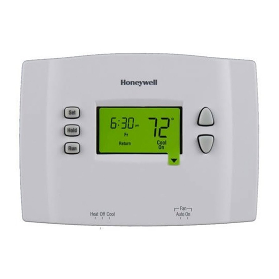
- Page 1 Quick Installation Guide 6 : 30 Hold Cool Return Heat Off Cool Auto On M38852 RTH2510/RTH2410 Programmable Thermostat 69-2421ES-05...
- Page 2 Quick Installation Guide Identify System Type This thermostat is compatible with the following sys- This thermostat is compatible with the following sys- tems: tems: • Gas, oil or electric furnace • Central air conditioner • Hot water system with or without pump •...
- Page 3 RTH2510/RTH2410 Turn Off Power to Heating/ Cooling System M38853 69-2421ES—05...
- Page 4 Quick Installation Guide Remove Old Thermostat Remove old thermostat but leave wallplate with wires attached. MERCURY NOTICE Do not put your old thermostat in the trash if it contains mercury in a sealed tube. Contact your local waste Do not remove management authority wallplate yet for instructions regarding...
- Page 5 RTH2510/RTH2410 Identify Wires If any wires are not attached to your old thermostat or are attached to a terminal marked C or C1, they will not be connected to your new thermostat. Wrap the bare metal end of each of these wires with electrical tape, so it cannot touch and short other wires.
- Page 6 Quick Installation Guide Mount New Wallplate 1. Loosen the locking screw at the bottom of the thermostat. Note that the screw is captive and cannot be removed from the wallplate. 2. Separate the thermostat from the wallplate as per Figure 1. 3.
- Page 7 RTH2510/RTH2410 Connect Wires: Conventional Systems (typical wiring) 1. Match each labeled wire with the terminal having the same letter. REMOVE JUMPER IF YOU HAVE BOTH R AND RC WIRES W/AUX M32148A 2. Loosen the terminal screws using a screwdriver, insert the wires, then tighten the screws.
- Page 8 Quick Installation Guide Connect Wires: Conventional Systems (alternate wiring) W/AUX REMOVE JUMPER BETWEEN R AND RC IF YOU HAVE WIRES ON BOTH R AND RC. DO NOT USE C, C1, OR X WIRE. DO NOT USE B WIRE IF YOU ALREADY HAVE 0 WIRE. WRAP BARE END OF WIRE WITH ELECTRICAL TAPE.
- Page 9 RTH2510/RTH2410 Connect Wires: Heat Pump Systems with Auxiliary/Backup Heat (typical wiring) 1. Match each labeled wire with the terminal having the same letter. W/AUX M32150A 2. Loosen the terminal screws using a screwdriver, insert the wires, then tighten the screws.
- Page 10 Quick Installation Guide Connect Wires: Heat Pump Systems with Auxiliary/Backup Heat (alternate wiring) W/AUX LEAVE JUMPER IN PLACE, CONNECTING R AND RC. THIS THERMOSTAT CANNOT BE USED IF YOUR OLD THERMOSTAT HAD ANY TWO OF THE FOLLOWING WIRES R, RC, V, OR VR. DO NOT USE C OR X WIRE.
- Page 11 RTH2510/RTH2410 Set Heating Fan Control Set jumper JP1, on the back of the thermostat, if you have connected a wire to the G terminal. M38858 Leave the jumper in this factory-set position if you have a gas or oil furnace.
- Page 12 Quick Installation Guide Set Heat Pump Reversing Valve Set jumper JP2, on the back of the thermostat, if you have a heat pump. M38858 Leave the jumper in this factory-set position if you have connected O wire to the O/B terminal. Place the jumper to this position if you have connected B wire to the O/B terminal.
- Page 13 RTH2510/RTH2410 Install Batteries and Thermostat 1. Install 2 AAA batteries on the back of the thermostat. M38855 2. Align the two brackets on the top of the thermostat with the corresponding slots on the top of the wallplate. 3. Push the thermostat against the wallplate.
-
Page 14: Table Of Contents
Advanced Installation System setup ..................13 Temperature display..............14 Time display format ...............15 Heating cycles per hour ...............16 Compressor protection ..............17 Early start ..................18 System startup ................19 Customer assistance..............20 Limited warranty ................21... -
Page 15: System Setup
RTH2510/RTH2410 System setup Follow the procedure below to personalize and config- ure the thermostat according to the heating/cooling system. 1. Press and hold the s and t buttons simultaneously (for three seconds) until the display appears as shown below. Function number... -
Page 16: Temperature Display
Advanced Installation Guide Temperature display Press the s or t button to select Fahrenheit or Celsius temperature display. M38859 0 Fahrenheit temperature display (°F) 1 Celsius temperature display (°C) When correct setting is selected, press both s and t to display next function. 69-2421ES—05... -
Page 17: Time Display Format
RTH2510/RTH2410 Time display format Press the s or t button to select 12-hour display or 24-hour display. M38860 0 12-hour display 1 24-hour display When correct setting is selected, press both s and t to display next function. 69-2421ES—05... -
Page 18: Heating Cycles Per Hour
Advanced Installation Guide Heating cycles per hour Note: Make sure system switch is in the heat position. Press the s or t button to select your heating system and optimize its operation: 2 to 6 cycles per hour M38861 5 12 min, Gas or oil furnace. Use this setting if you have a standard gas or oil furnace that is less than 90% efficient. -
Page 19: Compressor Protection
RTH2510/RTH2410 Compressor Protection Press the s or t button to select compressor protec- tion: M38862 1 On 0 Off Damage can occur if the compressor is restarted too soon after shutdown. This fea- ture forces the compressor to wait 5 minutes before restarting. -
Page 20: Early Start
Advanced Installation Guide Early start Press the s or t button to select Early start: M38863 1 On 0 Off Early start allows the thermostat to “learn” how long your furnace or air conditioner takes to reach the set temperature. Simply program the desired times and desired tem- peratures into the schedule. -
Page 21: System Startup
RTH2510/RTH2410 System startup Press the s or t button to select System startup: M38864 0 Conventional system (1H1C) 1 Heat pump system with auxiliary/backup heat (2H1C) When correct setting is selected, press the s and t buttons to save any changes and exit the menu. -
Page 22: Customer Assistance
Advanced Installation Guide Customer assistance For assistance with this product, please visit resideo.com or call Resideo Customer Care toll-free at 1-800-468-1502 69-2421ES—05... -
Page 23: Limited Warranty
RTH2510/RTH2410 One-year limited warranty Resideo warrants this product, excluding battery, to be free from defects in workmanship or materials, under normal use and service, for a period of one (1) year from the date of first purchase by the original purchaser. - Page 24 Printed in United States © 2022 Resideo Technologies, Inc. All rights reserved. The Honeywell Home trademark is used under license from Honeywell International, Inc. This product is manufactured by Resideo Technologies, Inc. and its affiliates. Todos los derechos reservados. La marca comercial Honeywell Home se utiliza bajo licencia de Honeywell International, Inc.
- Page 25 Guía de instalación rápida 6 : 30 Hold Cool Return Heat Off Cool Auto On M38852 RTH2510/RTH2410 Termostato programable...
- Page 26 Guía de instalación rápida Identifique el tipo de sistema Este termostato es compatible con los siguientes sistemas: • Calefactor a gas, aceite o eléctrico • Aire acondicionado central • Sistema a agua caliente con o sin bomba • Sistema de milivoltios •...
- Page 27 RTH2510/RTH2410 Desconecte la alimentación en el sistema de calefacción/ refrigeración M38853 69-2421ES—05...
- Page 28 Guía de instalación rápida Remueva su viejo termostato Retire el termostato existente pero deje la placa de montaje con los cables adheridos. ADVERTENCIA SOBRE EL MERCURIO: No arroje el viejo termostato a la basura si contiene mercurio en un tubo sellado.
- Page 29 RTH2510/RTH2410 Identifique los cables Si en el viejo termostato hubiera cables no conectados o conectados a un terminal marcado C o C1, estos cables no se usarán con el nuevo termostato. Recubra el extremo de metal desnudo de cada uno con cinta aisladora para que no puedan tocarse y producir un corto circuito.
- Page 30 Guía de instalación rápida Instalar la nueva placa mural 1. Aflojar los tornillos de la base del termostato. El tornillo está cautivo y no se lo puede retirar de la base. 2. Separar el termostato de la placa mural como se indica en la Figura 1.
- Page 31 RTH2510/RTH2410 Conecte los cables: Sistemas convencionales (conexión típica) 1. Hacer coincidir cada cable etiquetado con el terminal de la misma letra. RETIRE EL PUENTE SI HAY CABLES R Y RC. W/AUX MS32148A 2. Aflojar los tornillos del terminal con un destornillador, introducir los cables y reajustar los tornillos.
- Page 32 Guía de instalación rápida Conecte los cables: Sistemas convencionales (conexión alternativa) W/AUX SI LOS CABLES ESTÁN CONECTADOS CON LOS TERMINALES R Y RC, RETIRE EL PUENTE. NO USAR LOS CABLES C, C1 O X. NO USAR EL CABLE B SI YA EXISTE UN CABLE O. ENVOLVER EL EXTREMO DESNUDO DE LOS CABLES CON CINTA AISLADORA.
- Page 33 RTH2510/RTH2410 Conecte los cables: Sistemas de bombas de calor con calef-actor auxiliar (conexión típica) 1. Hacer coincidir cada cable etiquetado con el terminal de la misma letra. W/AUX M32150A 2. Aflojar los tornillos del terminal con un destornillador, introducir los cables y reajustar los tornillos.
- Page 34 Guía de instalación rápida Conecte los cables: Sistemas de bombas de calor con calefactor auxiliar (conexión alternativa) W/AUX DEJE EL EMPALME EN LUGAR, ENTRE TERMINALES DE R Y RC. NO PUEDE USARSE ESTE TERMOSTATO SI EL VIEJO TERMOSTATO TUVIERA DOS DE LOS SIGUIENTES CABLES: R, RC, V O VR. NO USAR LOS CABLES C O X.
- Page 35 RTH2510/RTH2410 Ajuste el control del ventilador Ajuste el puente JP1, que está en la parte de atrás del termostato, si se conectó un cable al terminal G. M38858 Deje el puente en este ajuste de fábrica en el caso de una estufa a gas o a aceite Ponga el puente en esta posición en el caso de...
- Page 36 Guía de instalación rápida Ajuste de la válvula de inversión Ajustar el puente JP2, en la parte de atrás del termo- stato, en el caso de una bomba de calor. M38858 Dejar el puente en este ajuste de fábrica si hay un cable O conectado al terminal O/B.
- Page 37 RTH2510/RTH2410 Instalación de las pilas y del termostato 1. Instalar 2 pilas AAA en la parte de atrás del termostato. M38855 2. Alinear las dos lengüetas de la parte superior del termostato con las ranuras correspondientes de la parte superior de la placa mural.
- Page 38 Guía de instalación avanzada Cómo cambiar la configuración ..........13 Visor de la temperatura ...............14 Formato de la hora ................15 Ciclos de calefacción por hora ...........16 Protección del compresor ............17 Encendido anticipado ..............18 Configuración del sistema............19 Asistencia al cliente ...............20 Garantía limitada ................21...
- Page 39 RTH2510/RTH2410 Configuración del sistema El procedimiento a continuación permite personalizar y configurar el termostato según el sistema de calefacción/enfriamiento. 1. Presionar los botones s y t al mismo tiempo (3 seg.) hasta que se vea lo que se indica en la ilustración.
-
Page 40: Visor De La Temperatura
Guía de instalación avanzada Visor de la temperatura Presione los botones para optar entre visualizar la temperatura en grados Fahrenheit o en grados Celsius. M38859 0 Visualización de la temperatura en Fahrenheit (°F) 1 Visualización de la temperatura en Centígrados (°C) Cuando haya elegido la configuración correcta, presione s y t para mostrar la función siguiente. -
Page 41: Formato De La Hora
RTH2510/RTH2410 Formato de la hora Presione los botones para optar entre visualizar la 12 horas o 24 horas. M38860 0 Visualización de la 12 horas 1 Visualización de la 24 horas Cuando haya elegido la configuración correcta, presione s y t para mostrar la función siguiente. -
Page 42: Ciclos De Calefacción Por Hora
Guía de instalación avanzada Ciclos de calefacción por hora Nota: cerciórese que el interruptor del sistema esté en la posición de calor. Presione los botones para seleccionar el sistema de calefacción y optimizar la operación: 2 a 6 ciclos por hora M38861 5 12 min. -
Page 43: Protección Del Compresor
RTH2510/RTH2410 Protección del compresor Presione los botones para seleccionar Protección del compresor: M38862 1 Desconectada 0 Conectada El compresor puede dañarse si se pusiera en marcha enseguida después de haberse detenido. Esta función lo obliga a esperar 5 minutos antes de ponerse en marcha nuevamente, mientras los mensajes Cool On o Heat On parpadean en la pantalla. -
Page 44: Encendido Anticipado
Guía de instalación avanzada Encendido anticipado Presione los botones para seleccionar Encendido anticipado: M38863 1 Desconectada 0 Conectada La función encendido anticipado permite que el termostato “aprenda” cuánto le lleva a la estufa o al aire acondicionado para cumplir con la hora y la temperatura del horario. -
Page 45: Configuración Del Sistema
RTH2510/RTH2410 Configuración del sistema Presione los botones para seleccionar Configuración del sistema: M38864 0 Sistema convencional (1H1C) 1 Bomba de calor con calefacción auxiliar (2H1C) Cuando haya elegido la configuración correcta, presionar s y t para salvaguardar los cambios y salir del menú. -
Page 46: Asistencia Al Cliente
Guía de instalación avanzada Asistencia al cliente Si necesita asistencia, visite resideo.com o llame al número gratuito de atención al cliente de Honeywell al 1 800 468-1502. 69-2421ES—05... -
Page 47: Garantía Limitada
RTH2510/RTH2410 Garantía limitada de 1 año Resideo garantiza que este producto, excluyendo la batería, no tiene defectos en la mano de obra ni en los materiales en condiciones de uso y servicio normales durante un período de un (1) ano desde la fecha de compra por parte del comprador original. - Page 48 Impreso en EE. UU. © 2022 Resideo Technologies, Inc. All rights reserved. The Honeywell Home trademark is used under license from Honeywell International, Inc. This product is manufactured by Resideo Technologies, Inc. and its affiliates. Todos los derechos reservados. La marca comercial Honeywell Home se utiliza bajo licencia de Honeywell International, Inc.
Need help?
Do you have a question about the RTH2510 and is the answer not in the manual?
Questions and answers