
Subscribe to Our Youtube Channel
Related Manuals for Stoelting F231


Summary of Contents for Stoelting F231
- Page 1 Model F231 SERVICE MANUAL Manual No. 513659 Rev.1...
- Page 2 https://appliancetechmanuals.com...
- Page 3 https://appliancetechmanuals.com INTELLITEC2 FIRMWARE VERSION UPDATE LOG The list below shows the history of the fi rmware versions in the IntelliTec2 control. The information in this manual refers to Version 20.27. VERSION 20.27 - CURRENT VERSION Released on 12/28/10 • Added Unit Serial Number to Service Contact Information and Modify Contact Information •...
- Page 4 https://appliancetechmanuals.com VERSION 17.19 (CONTINUED) • Storage CutOut changed to 32°F (was 31°F) • Storage Offset changed to 4°F (was 2°F) • Storage Off Time changed to 13 min (was 2 min) • Storage On Time changed to 130 sec (was 200 sec) •...
- Page 5 If problems develop or questions arise in connection with installation, operation, or servicing of the machine, contact the com- pany at the following location: STOELTING 800-558-5807 502 Hwy. 67 Kiel, WI 53042 Fax: 920-894-7029 © 2011 Stoelting, LLC, All Rights Reserved...
- Page 6 CAUTION If you need to replace a part, use genuine Stoelting The signal word “CAUTION” indicates a potentially parts with the correct part number or an equivalent hazardous situation, which, if not avoided, may result part.
-
Page 7: Table Of Contents
https://appliancetechmanuals.com TABLE OF CONTENTS Section Description Page Description and Specifi cations Description ....................1 Specifi cations ..................... 2 Installation Instructions Safety Precautions ..................5 Shipment and Transit .................. 5 Machine Installation ..................5 Installing Permanent Wiring ................ 5 Initial Set-Up and Operation Operator’s Safety Precautions .............. - Page 8 https://appliancetechmanuals.com Section Description Page Refrigeration System Refrigeration System .................. 25 Refrigerant Recovery and Evacuation ............25 Refrigerant Charging .................. 26 Compressor ....................27 Condenser ....................28 Valves ......................28 Thermostatic Expansion Valve (TXV) ..............28 Check Valve ......................29 High Pressure Cutout ................... 29 Hot Gas Bypass ....................
-
Page 9: Description
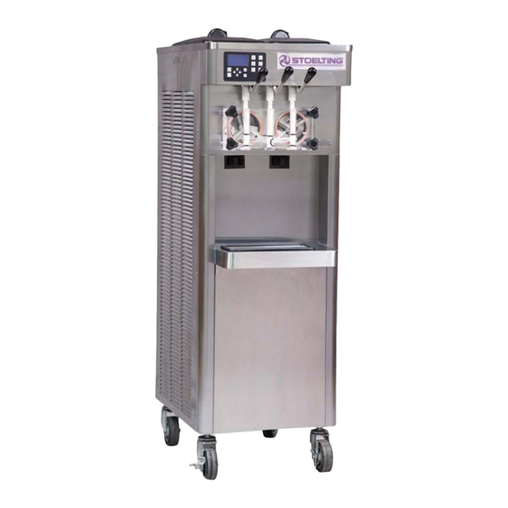
SECTION 1 INTRODUCTION 1.1 DESCRIPTION The Stoelting F231 fl oor machine is gravity fed. The machine is equipped with the IntelliTec2 control which provides a uniform product. The F231 is designed to operate with almost any type of commercial soft serve or non-dairy mixes available, including: ice milk, ice cream, yogurt, and frozen dietary desserts. -
Page 10: Specifications
SPECIFICATIONS Figure 1-2 Specifi cation Model F231 Dimensions Machine with crate width 19-1/4’’ (48,9 cm) 40-1/4’’ (102,2 cm) height 58-1/4’’ (148,0 cm) 64-1/2’’ (163,8 cm) depth 28’’ (71,1 cm) 33-1/4’’ (84,5 cm) Weight 400 lbs (181,4 kg) 490 lbs (222,2 kg) - Page 11 Menu Display F231 Basic Enable Control Consistency/Consistency CutOut Consist Offset CutIn Consist Offset CutIn Temp 19.5 °F CutOut Temperature 19 °F Cycles In Serve Mode Advanced Standby On Time 10 sec Standby Off Time 360 sec Standby Time 120 min...
- Page 12 https://appliancetechmanuals.com IntelliTec2 Control Modes of Operation PUSH TO FREEZE or Spigot Pull PUSH TO FREEZE or Spigot Pull PUSH TO FREEZE or Spigot Pull Serve Mode / Serve 2 Mode Standby Mode Sleep 1 Mode Sleep 2 Mode Sleep 2 CutIn Sleep 2 CutIn Standby Off Time...
-
Page 13: Installation Instructions
10 days and request inspection. The customer must place claim for damages and/or shortages 2.4 INSTALLING PERMANENT WIRING in shipment with the carrier. Stoelting, Inc. cannot make any claims against the carrier. To install wiring follow the steps below: Refer to the nameplate on the side panel of the 2.3 MACHINE INSTALLATION... - Page 14 https://appliancetechmanuals.com...
-
Page 15: Initial Set-Up And Operation
https://appliancetechmanuals.com SECTION 3 INITIAL SET-UP AND OPERATION 3.1 OPERATOR’S SAFETY PRECAUTIONS 3.2 OPERATING CONTROLS AND INDICATORS SAFE OPERATION IS NO ACCIDENT; observe these Before operating the machine, it is required that the op- rules: erator know the function of each operating control. Refer to Figure 3-1 for the location of the operating controls on Know the machine. -
Page 16: Disassembly Of Machine Parts
D. MIX LOW LIGHTS Mix sanitizer in quantities of no less than 2 The mix low lights are located at the back of the F231. gallons of 90° to 110°F (32°C to 43°C) water. Any There is a light for each freezing cylinder. A steady light sanitizer must be used only in accordance with signifi... -
Page 17: Cleaning Disassembled Parts
https://appliancetechmanuals.com B. DISASSEMBLY OF FRONT DOOR 3.4 CLEANING DISASSEMBLED PARTS Turn the machine off by pressing the Main Freezer Disassembled machine parts require complete cleaning, Power Off/On button on the IntelliTec2 control. sanitizing and air drying before assembling. Local and state health codes will dictate the procedure required. -
Page 18: Assembling The Machine
https://appliancetechmanuals.com 3.7 ASSEMBLING MACHINE Apply a thin layer of sanitary lubricant to the inside and outside of the auger support bushing. Install To assemble the machine parts, refer to the following steps: the bushing onto the auger support and install the NOTICE auger support into the front of the auger. -
Page 19: Freeze Down And Operation
https://appliancetechmanuals.com Check for leaks. NOTE 1. Check for leaks at the front door seals. The machine has a standby and sleep mode. After a preset number of freezing cycles, it will enter the 2. Check the drain tray located under the front standby mode (followed by sleep mode) and remain door for leaks coming from the rear of the rear there until someone draws product or presses the... - Page 20 https://appliancetechmanuals.com...
-
Page 21: Maintenance And Adjustments
The default is Manager Press the right arrow, up arrow then the Stoelting Technical Customer Service. The Manager and SEL button Technician levels can change the default by selecting the Modify Contact Information option or by uploading... -
Page 22: Performance Screens
https://appliancetechmanuals.com D. Fine Consistency Adjustment B. Performance (2 of 2) Product consistency can be adjusted by the Associate level by using the Fine Consistency Adjustment screen. The Performance screens display the current status of Increasing the Fine Consistency number increases the the machine. - Page 23 https://appliancetechmanuals.com The Enable Control setting determines the cutin and D. Advanced Settings (2 of 2) cutout style. The options are Consistency-Consistency, Temperature-Consistency or Temperature-Temperature. Setting the control to Consistency-Consistency enables Serve 2 Mode (instead of Serve 1 Mode). Serve 2 Mode extends the post stir to prevent short cycling the com- pressor and a possible misread of the consistency in the freezing cylinder.
-
Page 24: Utilities Screens
https://appliancetechmanuals.com F. Storage Settings (2 of 2) H. Time and Date This Storage Settings menu contains storage refrigeration parameters and is available to the Manager and Techni- The Time and Date menu shows the time and date set- cian levels. Press the left arrow to go to the fi rst screen. tings. - Page 25 https://appliancetechmanuals.com A. Product Selection E. Clean Options The Product Selection screen changes CutIn Consis- tency and CutOut Consistency to a predetermined value depending on the product type. The Clean Options Menu gives access to the Clean His- tory Log and Clean Lockout options. B.
- Page 26 https://appliancetechmanuals.com The Testing and Manual Operation menu provides access G. Motor Calibration for individual components to be energized to assist with troubleshooting. There are also test monitoring screens that provide details of the machine status during testing. Any energized component will deenergize after leaving the Testing and Manual Operations menu.
-
Page 27: Errors & Statistics Screens
https://appliancetechmanuals.com J. Restore Motor Table Defaults B. Machine Statistics (2 of 10) The Restore Motor Table Defaults screen allows you to The Machine Statistics screen 2 of 10 shows the low mix restore the motor defaults. running time. This is the total time, including serve mode and sleep mode, that the freezing cylinder was operating with a low mix error. - Page 28 https://appliancetechmanuals.com E. Machine Statistics (5 of 10) H. Machine Statistics (8 of 10) The Machine Statistics screen 5 of 10 gives the estimated The Machine Statistics screen 8 of 10 shows the total run serve amount of the freezing cylinder based on the time time for the pump and counts the total cycles.
-
Page 29: Updating Firmware
NOTE Press the up or down arrow to scroll through the errors. If the display does not show the "Stoelting Food- Select the Status at Time of Error option to view data for service Equipment" text, make sure the .rom fi le the time the error occurred. -
Page 30: Drive Belt Tension Adjustment
Service Contact Information screen. MACHINES) Scroll to the serial number and press the SET The F231 has an air-cooled or water-cooled condenser. button. Enter the serial number for the machine by scrolling through the numbers. The serial number The air-cooled condenser is a copper tube and aluminum is found on the information plate located on the fi... -
Page 31: Preventative Maintenance
https://appliancetechmanuals.com 4.11 PREVENTATIVE MAINTENANCE It is recommended that a preventative maintenance schedule be followed to keep the machine clean and operating properly. The following steps are suggested as a preventative maintenance guide. The United States department of agriculture and the food and drug administration require that lubricants used in food zones be certifi... - Page 32 https://appliancetechmanuals.com...
-
Page 33: Refrigeration System
5.1 REFRIGERATION SYSTEM NOTE For qualifi ed service personnel only. Anybody work- The F231 refrigeration systems have two functions: ing with refrigerants must be certifi ed as a Techni- Medium-Temperature - Maintaining mix cian TYPE I as required by 40 CFR 82 Subpart F temperature in the hopper. -
Page 34: Refrigerant Charging
Close any open ports in the refrigeration system. NOTE Connect a vacuum gauge to one of the Schrader The refrigeration systems of F231 is critically valves next to an evaporator. charged. Be sure to charge the system to the weight Connect the evacuation unit to the suction and listed on the machine’s information plate. -
Page 35: Compressor
5.4 COMPRESSOR To check if windings are shorted to ground, connect one ohmmeter lead to a bare metal part on the The F231 has a hermetic reciprocating compressor (Refer compressor (such as any copper line leading to to Figure 5-2). -
Page 36: Condenser
5.5 CONDENSER NOTE The F231 comes with either an air-cooled or a water- The TXV is the LAST component to adjust in the cooled condenser. The capacity of the machine is directly refrigeration system. -
Page 37: Check Valve
https://appliancetechmanuals.com TXV REPLACEMENT To replace the TXV, perform the following procedures: Position the TXV, with a heat sink, into the system. With the suction and discharge ports open, braze the TXV into the system. Remove the heat sink from the TXV. Replace insulation to the TXV and surrounding lines. -
Page 38: Hot Gas Bypass
https://appliancetechmanuals.com D. HOT GAS BYPASS HOT GAS BYPASS REMOVAL The hot gas bypass valve is installed parallel to the com- Remove the left side panel. pressor and helps to regulate the compressor temperature Recover refrigerant charge per instructions in (Refer to Figure 5-7). When the cab evaporator is the only Section 5.2. -
Page 39: Water Valve (Water Cooled Models Only)
https://appliancetechmanuals.com If the gauge does not read 60 ±2 then adjustment The exit water temperature should be 95-107°F. is needed. If the water temperature and high side pressure Remove the plastic cap and loosen the locknut are too low, the opening point pressure should on the EPR. -
Page 40: Solenoid
https://appliancetechmanuals.com 5.7 SOLENOID Solenoid valves are installed on the liquid and suction lines of each freezing cylinder evaporator and on the liquid line of the hopper evaporators (Refer to Figure 5-10 and Figure 5-11). A solenoid valve has a magnetic coil that, when energized, lifts a plunger and allows refrigerant to fl... -
Page 41: Filter Drier
https://appliancetechmanuals.com SOLENOID MAGNETIC COIL REMOVAL 5.8 FILTER DRIER Remove the side panel. The fi lter drier must be replaced every time the refrigeration system is opened for service. A new fi lter drier improves Disconnect the electrical wires. operation of the entire refrigeration system by stopping Remove the retainer screw from the top of the the circulation of moisture and by removing harmful con- solenoid and pull the magnetic coil off. -
Page 42: Capillary Tube
https://appliancetechmanuals.com 5.9 CAPILLARY TUBE The capillary tube meters refrigerant fl ow in the mix line evaporator (Refer to Figure 5-13). The amount of fl ow is dependent on the length and ID of the capillary tube as well as the refrigerant charge. Figure 5-13 Capillary Tube and Drier Assembly CAPILLARY TUBE REMOVAL NOTE... -
Page 43: Electrical And Mechanical Control Systems
The boards are connected by two screws. CONTACTORS The F231 has a total of three contactors. One for the com- pressor and one for each drive motor. The contactors are located in the electrical box behind the right side panel. -
Page 44: Drive Motor
DRIVE MOTOR The F231 has two drive motors. They are used to rotate the auger assemblies. An internal, normally closed, cen- trifugal switch starts the drive motor. The motors have an internal thermal overload. A. DRIVE MOTOR TEST Turn the machine off by pressing the Main Power Off/On button and disconnect the machine from the electrical supply. -
Page 45: Capacitors
https://appliancetechmanuals.com CAPACITORS Pull the capacitor out of its holder and replace. Connect the leads to the terminals of the new The compressor start and run capacitors are only on single capacitor. phase machines. They are accessible by removing the right side panel. GEARBOX The start and run capacitors for the drive motors are mounted directly onto each motor body. -
Page 46: Spigot Switch
https://appliancetechmanuals.com Spigot Glide Figure 6-5 Spigot Cam Assembly (Center Spigot) SPIGOT SWITCH TEST - ADJUSTMENT NOTE Figure 6-4 Air Cooled Condenser Adjustments to the spigot switch should be done B. FAN MOTOR INSTALLATION after the product is at consistency in “Serve Mode” or when the machine is empty. -
Page 47: Temperature Control Sensor
https://appliancetechmanuals.com TEMPERATURE CONTROL SENSOR The temperature control sensor is a thermistor used to sense the temperature of the suction line. As the suction line temperature increases, the internal resistance of the thermistor will decrease. Refer to Figure 6-7 for the relationship between sensor resistance and temperature. - Page 48 https://appliancetechmanuals.com...
-
Page 49: Troubleshooting
https://appliancetechmanuals.com SECTION 7 TROUBLESHOOTING 7.1 ERROR CODES Ice crystals in the hopper can clog the mix inlet regulator and prevent mix from entering When the machine experiences a problem, one of the the freezing cylinder. Thoroughly thaw mix per following error codes will be displayed on the control manufacturer's recommendations. - Page 50 The Freezing Cylinder Sensor Error (E5) indicates The Hopper Sensor Error (E6) will not occur on a failure of the barrel sensor or if the sensor is the F231. out of range. If the control panel displays an E5, ERROR CODE 7 - DRIVE MOTOR...
- Page 51 ERROR CODE 11 - PRIME The Prime Error (E11) will not occur on the F231. ERROR CODE 12 - LEFT HOPPER SENSOR The Left Hopper Sensor Error (E12) indicates a failure of the hopper sensor or if the sensor is out of range.
-
Page 52: Troubleshooting - Machine
https://appliancetechmanuals.com 7.3 TROUBLESHOOTING - MACHINE PROBLEM POSSIBLE CAUSE REMEDY 1 Power to machine is off. 1 Supply power to machine. Machine does not 2 Freeze-up (auger will not turn). 2 Turn Clean/Off/On switch Off for 15 minutes, run. then restart. 3 Front door not in place. -
Page 53: Replacement Parts
Decal - Adequate Ventilation 3” 324594 Decal - Attention Heat Sensitive 324686 Decal - Danger Automatic Start 324803 Decal - Domed Stoelting Logo (Large) (Header Panel) 324908 Decal - Rear Light 324909 Decal - USB Port 508048 Lubricant - Spline (2 oz Squeeze Tube) -
Page 54: Auger Shaft And Faceplate Parts
https://appliancetechmanuals.com 8.3 AUGER SHAFT AND FACEPLATE PARTS 694255 381804 149003 666786 624678-5 4157968 3170644 625133 2149243-01 2177428 624677-5 3159696 3158086 624598-5 624664-5 624614-5 744262 417006 744273... - Page 55 https://appliancetechmanuals.com 8.3 AUGER SHAFT AND FACEPLATE PARTS (CONTINUED) Part Description Quantity 149003 Bushing - Front Auger Support 232734 Cap - Rosette - Teardrop 314453 Cover - Hopper 381804 Auger Flight 417006 Grid - Drip Tray (Metal) 482019 Knob - Front Door (Black) 624598-5 O-Ring - Outside Spigot - Black (5 Pack) 624614-5...
-
Page 56: Internal Components
https://appliancetechmanuals.com 8.4 INTERNAL COMPONENTS 2202316 231078 762454 762490 763422 763482 231095 272065 342004 763423 521513 618142 521514 618157 521516 763017 230633 230649 614233 231084 231079 598296 718794 231107 295112 762978 152231 598031 342020 522858-SV 458003 282032 284084 162077 522291... - Page 57 https://appliancetechmanuals.com 8.4 INTERNAL COMPONENTS (CONTINUED) Part Description Quantity 152234 Belt - Gripnotch (AX33) (1 per Side) 162077 Blade - Fan (Air-Cooled Condenser) 229148 Cable - IntelliTec2 (Control Board to Display Board) 230633 Capacitor - Run (50 Hz) 230649 Capacitor - Start (50 Hz) 231079 Capacitor - Start 231084...
-
Page 58: Spigot Assembly
https://appliancetechmanuals.com 8.5 SPIGOT ASSEMBLY 718733 696044 570961 2158082 428045 2187805 Part Description Quantity 428045 Knob - Spigot Handle (Black) 570961 Pin - Cotterless Clevis (Spigot Cam) 696044 Spring - Torsion (Spigot Cam) 718773 Switch - Limit (Spigot Cam) 2158082 Glide - Spigot Socket 2187805 Handle - Spigot (Handle Only) 8.6 FRONT... -
Page 59: Wiring Diagrams
https://appliancetechmanuals.com 8.7 WIRING DIAGRAMS... - Page 60 https://appliancetechmanuals.com...
Need help?
Do you have a question about the F231 and is the answer not in the manual?
Questions and answers
Good morning, my soft serve ice cream machine never goes into “serve mode”, continually says “freezing”. All parts seemed to work correctly. What would be the possible cause of this situation?
The Stoelting F231 soft serve ice cream machine may not enter "serve mode" and continue displaying "freezing" due to the following possible causes:
1. Machine is in Sleep Mode – The machine may still be in night mode or standby mode. Ensure that "Freeze Left" and "Freeze Right" buttons are pressed to activate serving mode.
2. Sensor Issues – A failure of the freezing cylinder sensor (Error Code 5) could cause the machine to malfunction. Restart the machine by turning it off and on. If the issue persists, contact an authorized Stoelting distributor.
3. Refrigeration Problem – If the refrigeration system is not working properly, the product may not freeze correctly. A service check may be required.
4. Mix Not Freezing Properly – If the bars indicating freezing progress are not appearing, the machine may not be cooling efficiently due to issues like improper air ventilation or a dirty condenser.
If troubleshooting does not resolve the issue, professional service may be needed.
This answer is automatically generated