
Related Manuals for Xycom XVME-977


Summary of Contents for Xycom XVME-977
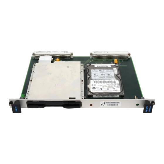
- Page 1 XVME-977 Hard Disk/Floppy Disk Module P/N 74977-001A © 1996 XYCOM, INC. XYCOM 750 North Maple Road Printed in the United States of America Saline, Michigan 48176-1292 Part Number 74977-001A (313) 429-4971...
- Page 2 This document is copyrighted by Xycom Incorporated (Xycom) and shall not be reproduced or copied without expressed written authorization from Xycom. The information contained within this document is subject to change without notice. Xycom does not guarantee the accuracy of the information and makes no commitment to keeping it up to date.
-
Page 3: Table Of Contents
Module Features .............................1-1 Specifications ............................1-1 Hardware Specifications........................1-2 Environmental Specifications ......................1-2 Chapter 2 – Installation Installing into a VMEbus Card Cage .......................2-1 Configuring the XVME-977 ........................2-3 VMEbus Interface ...........................2-4 Pinouts ..............................2-4 P1 Connector ............................2-4 P2 Connector ............................2-5 Floppy Drive Connector (P3) .......................2-6... -
Page 5: Chapter 1 - Introduction
VMEbus systems. This module is built to commu- nicate with Xycom’s XVME-65x VMEbus PC/AT processors. Power for the XVME-977 is provided by the P1 and P2 connectors. Signals are routed through P2. Figure 1-1 illustrates this in a block diagram of the XVME-977. -
Page 6: Hardware Specifications
Table 1-2. Floppy Drive Hardware Specifications Characteristic Specification Interface PC/AT-compatible Compatibility 3.5", 1.44 Mbyte Environmental Specifications Table 1-3 provides the environmental specifications for the XVME-977. Table 1-3. Environmental Specifications Characteristic Specification Temperature Operating 0° to 50° C (0° to 122° F) Non-operating -40°... -
Page 7: Chapter 2 - Installation
Installing into a VMEbus Card Cage The XVME-977 occupies only one double-high VMEbus slot, and fits into any standard 6U VMEbus card cage. Like all of Xycom’s modules, the XVME-977 is designed to comply with all electrical VMEbus backplane specifications. This module only draws current from the +5 volt power supply. - Page 8 XVME-977 Hard Disk/Floppy Disk Module Figure Chapter 2 -1. XVME-977 Installation...
-
Page 9: Configuring The Xvme-977
To install the XVME-977 in a card cage… 1. Turn off power to the chassis. 2. Connect the jumper cable from the CPU slot to the XVME-977 slot on the rear of the P2 backplane, as shown in Figure Chapter 2 -1. -
Page 10: Vmebus Interface
The VMEbus connector provides power (+5 V and GND). The bus grant in and bus grant out are connected together, and the IACKIN* and IACKOUT* are connected together. Pinouts This section describes the pinouts for each of the four connectors on the XVME-977. P1 Connector BG0IN*... -
Page 11: P2 Connector
Chapter 2 – Installation P2 Connector RES (NC) HDRESET* RES (NC) RES (NC) RES (NC) RES (NC) RES (NC) RES (NC) RES (NC) RES (NC) RES (NC) RES (NC) RES (NC) RES (NC) RES (NC) RES (NC) RES (NC) RES (NC) RES (NC) RES (NC) RES (NC) -
Page 12: Floppy Drive Connector (P3)
XVME-977 Hard Disk/Floppy Disk Module Floppy Drive Connector (P3) Signal Signal FSTEP* IDX* FWD* FDS1* FWE* DCHG* FTK0* FWP* MO1* FRDD* FDIRC* FHS* Hard Drive Connector (P4) Signal Signal HDRQ DIOW* DIOR* HDRESET* IORDY HDACK* IRQ14 IOCS16* HD10 HD11 HD12... - Page 13 Index floppy drive, 1-2 hard drive, 1-2 block diagram, 1-1 VMEbus interface, 2-4 card cage installation, 2-1 connectors floppy drive, 2-6 hard drive, 2-6 P1, 2-4 P2, 2-5 environmental specifications, 1-2 features, module, 1-1 floppy drive connector, 2-6 hardware specifications, 1-2 specifications, setting, 2-3 hard drive connector, 2-6...
Need help?
Do you have a question about the XVME-977 and is the answer not in the manual?
Questions and answers