Table of Contents
Advertisement
Quick Links
UM0603
User manual
STEVAL-MKI005V1
demonstration kit for the LIS3LV02DL
Introduction
The STEVAL-MKI005V1 is a demonstration kit designed to provide the user with a
complete, ready-to-use platform to demonstrate the LIS3LV02DL low power 3-axis linear
accelerometer with digital output. The device includes a sensing element and an IC
interface capable of translating information from the sensing element into a measured signal
that can be used for external applications.
In addition to the MEMS sensor, the demonstration board features an ST7-USB
microcontroller that functions as a bridge between the sensor and the PC, on which it is
possible to use the graphical user interface (GUI) downloadable from the web site, or
dedicated software routines for customized applications.
This user manual describes the hardware included with the demonstration kit and provides
the information required to install and run the demonstration kit user interface.
For details regarding the features of the LIS3LV02DL sensor, please refer to the datasheet
for this device and application note AN2381.
November 2008
Rev 1
1/37
www.st.com
www.BDTIC.com/ST
Advertisement
Table of Contents

Related Manuals for ST STEVAL-MKI005V1


Summary of Contents for ST STEVAL-MKI005V1
- Page 1 LIS3LV02DL Introduction The STEVAL-MKI005V1 is a demonstration kit designed to provide the user with a complete, ready-to-use platform to demonstrate the LIS3LV02DL low power 3-axis linear accelerometer with digital output. The device includes a sensing element and an IC interface capable of translating information from the sensing element into a measured signal that can be used for external applications.
-
Page 2: Table Of Contents
Demonstration kit description ....... . . 5 STEVAL-MKI005V1 GUI installation ......7 PC system requirements . - Page 3 Revision history ......... . . 36 3/37 www.BDTIC.com/ST...
- Page 4 Top silk-screen of the STEVAL-MKI005V1 kit ........
-
Page 5: Demonstration Kit Description
UM0603 Demonstration kit description Demonstration kit description The STEVAL-MKI005V1 is a complete demonstration kit which allows users to evaluate the performance of the LIS3LV02DL low power 3-axis linear accelerometer with digital output. Figure The block diagram of the demonstration kit is shown in Figure 1. -
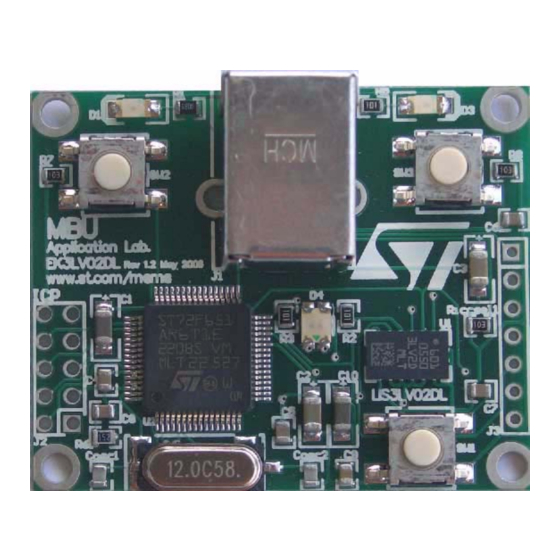
Page 6: Figure 2. Top Silk-Screen Of The Steval-Mki005V1 Kit
Figure 3. Board photograph Operation of the STEVAL-MKI005V1 demonstration kit requires the installation of a dedicated driver which is included on the installation pack, together with a GUI interface which allows simple interaction with the sensor. The steps required for driver and software installation are described in the following section. -
Page 7: Steval-Mki005V1 Gui Installation
UM0603 STEVAL-MKI005V1 GUI installation STEVAL-MKI005V1 GUI installation The installation of the graphical user interface (GUI) for the STEVAL-MKI005V1 requires two steps: installation on the PC the software downloaded to EK web page. installation of the Virtual COM driver needed to use the demonstration kit board. -
Page 8: Hardware Installation
Otherwise, the installation can be performed by following the instructions indicated Figure 6 Figure Figure 6. Driver installation using the device manager Right click on My Computer Right click on “ST MEMS UNIT” and choose Update driver 8/36 www.BDTIC.com/ST... -
Page 9: Figure 7. Usb Driver Installation Using The Hardware Update Wizard
Figure 7. USB driver installation using the hardware update wizard Once the installation is complete, a COM port number is assigned to the ST Virtual COM 8). This number should be retained as it is required to run the STEVAL-... -
Page 10: Figure 8. Virtual Com Driver Port Assignment
STEVAL-MKI005V1 GUI installation UM0603 Figure 8. Virtual COM driver port assignment 10/36 www.BDTIC.com/ST... -
Page 11: Graphical User Interface
UM0603 Graphical user interface Graphical user interface To execute the STEVAL-MKI005V1 demonstration software GUI: Click on Start > All Programs Select ST EVAL > STEVAL-MKI005V1 > Executables Launch the program “STEVAL-MKI005V1 Ver. 1.0” Figure The GUI main window appears as shown in Figure 9. -
Page 12: Connecting To The Virtual Com Port
Connecting to the Virtual COM port Before using the functions of the demonstration kit software it is necessary to open the connection with the STEVAL-MKI005V1 board. This is achieved through the following procedure: connect the STEVAL-MKI005V1 to the desired USB port (Figure 9 in the “Select COM”... -
Page 13: Options" Tab
Data Alignment Selection (DAS) - permits to decide between 12 bit right justified and 10, ref 8) 16 bit left justified representation of data coming from the device (Figure Figure 10. Options tab ref 1 ref 5 ref 2 ref 6 ref 3 ref 7 ref 8 ref 4 13/36 www.BDTIC.com/ST... -
Page 14: Register Setup" Tab
To write the values to the registers of the device, the user has to press the "Write" button after the "Default" one. Figure 11. Register setup tab ref 1 ref 2 ref 3 ref 4 ref 5 14/36 www.BDTIC.com/ST... -
Page 15: Bars" Tab
Click on the desired bar to zoom: the selected bar is shown at the center of the screen together with the acceleration as a numerical value. To return to the default view, click on the 13). center of the bar (Figure Figure 12. Bars tab 15/36 www.BDTIC.com/ST... -
Page 16: Plot" Tab
Operating Mode, Data Rate and Full scale To zoom in on the waveform, select the desired zone with the left button of the mouse 15). Click again with the right button to return to the default view. (Figure 16/36 www.BDTIC.com/ST... -
Page 17: Figure 14. Plot Tab
UM0603 Graphical user interface Figure 14. Plot tab ref 1 ref 2 17/36 www.BDTIC.com/ST... -
Page 18: Figure 15. Plot Tab - Zoom
3) Release the button to terminate the zoom procedure; a new area is visible on the screen 4) To return to the previous view, click on the screen with the RIGHT mouse button 18/36 www.BDTIC.com/ST... -
Page 19: Data" Tab
“Angle” (Figure from the “ADC Out” data Note: To increase data readability, the values shown in the boxes described above are based on an average of 50 samples. Figure 16. Data tab ref 1 ref 2 ref 3 19/36 www.BDTIC.com/ST... -
Page 20: Inclinometer" Tab
Graphical user interface UM0603 “Inclinometer” tab 17) represents the acceleration data measured by the sensor The Inclinometer tab (Figure in the form of an artificial horizon. Figure 17. Inclinometer tab Figure 18. Axis inclination +90° 0° horizontal plane x,y,z -90° 20/36 www.BDTIC.com/ST... -
Page 21: Map Browsing" Tab
Graphical user interface “Map Browsing” tab The Map browsing tab demonstrates the capability of using the acceleration data obtained from the sensor to scroll a map (or other type of document) on the screen. Figure 19. Map Browsing tab 21/36 www.BDTIC.com/ST... - Page 22 Y axis (ROLL) to move the map in right/left direction on the screen Figure 19 As the example in (b) shows, when the board is tilted along the X axes (positive ROLL), the map on the screen is moved to the right. 22/36 www.BDTIC.com/ST...
-
Page 23: Fft" Tab
Finally, two buttons are provided for each interrupt line to set the suggested default values for free-fall and wake-up detection. Those buttons are marked “Free-fall” and “Wake Up”, 21, ref 3). respectively (Figure 23/36 www.BDTIC.com/ST... -
Page 24: Direction Detection" Tab
The right side of the tab contains the registers used to configure the direction detection 22, ref 1), the threshold values expressed in mg 22, ref 2) and the function (Figure (Figure 22, ref 3). DD_SRC expressed as a bit vectors (Figure 24/36 www.BDTIC.com/ST... -
Page 25: Figure 22. Direction Detection Tab
UM0603 Graphical user interface Figure 22. Direction detection tab ref 1 ref 2 ref 3 25/36 www.BDTIC.com/ST... -
Page 26: Data Acquisition" Quick Start
“Data acquisition” quick start This section describes the basic steps that must be performed to acquire the acceleration data from the STEVAL-MKI005V1: connect the STEVAL-MKI005V1 to the USB port start the STEVAL-MKI005V1 GUI 9, ref 1) select the Virtual COM port and click on the “Connect” button... -
Page 27: Ek Lite
The purpose of the lite version is to provide the user a base for the development of a customized application. The lite version of the demonstration kit is started by launching the STEVAL-MKI005V1 lite executable file located in the STEVAL-MKI005V1 > Executables folder. -
Page 28: Mems Pointer
The buttons on the right side of the GUI and their related functions are described below: Connect/Disconnect control - selects the COM port on which the EK board is connected Acquisition control - starts and stops acquisition Exit - exits the MEMS pointer demo application 28/36 www.BDTIC.com/ST... -
Page 29: Left Side: Pointer Application Controls
“Up”, the pointer moves upward when the demonstration kit is tilted forward. Conversely, by selecting “Down” the pointer moves downward when the board is tilted backward. Pointer speed - sets the sensitivity of the pointer to the inclination of the board (ref 7) 29/36 www.BDTIC.com/ST... -
Page 30: Supported Commands
Terminal program integrated in the Windows operating system Create a new connection, enter a name (ex. “STEVAL-MKI005V1”), and click “OK” In the “Connect Using” field, select the Virtual COM port to which the USB port has been mapped, and click “OK”... -
Page 31: Start Command
Register read The *rAA command allows the contents of the LIS3LV02DL device registers in the demonstration kit board to be read. AA, expressed as hexadecimal value and written upper- case, represents the address of the register to be read. 31/36 www.BDTIC.com/ST... -
Page 32: Register Write
7.2.8 Device name The *dev command retrieves the name of the device mounted on the demonstration kit connected to the PC. For the STEVAL-MKI005V1, the returned value is “LIS3LV02DL”. 7.2.9 Firmware version The *ver command queries the demonstration kit and returns information on the version of the firmware loaded in the microprocessor. -
Page 33: Quick Start
This section shows the basic sequence of commands to start a data communication session and to retrieve the acceleration data from the demonstration kit: Connect the STEVAL-MKI005V1 to the USB port Start “Microsoft© Hyper Terminal” and configure it as described in section Inside the “Hyper Terminal”... -
Page 34: Schematic Diagram
Schematic diagram UM0603 Schematic diagram Figure The schematic diagram of the STEVAL-MKI005V1 demonstration kit is shown in Figure 25. Schematic diagram of the STEVAL-MKI005V1 board 100R LIS3LV02DL AM00685v1 AM00685v1 34/36 www.BDTIC.com/ST... -
Page 35: Bill Of Materials
UM0603 Bill of materials Bill of materials Table 2 lists the bill of materials for the STEVAL-MKI005V1 demonstration kit. Table 2. Bill of materials Designator Description Comment Footprint Capacitor 10 µC C1206_POL Capacitor 4 µC C1206_POL Capacitor 4 µC C1206_POL... -
Page 36: Revision History
Revision history UM0603 Revision history Table 3. Document revision history Date Revision Changes 07-Nov-2008 Initial release 36/36 www.BDTIC.com/ST... - Page 37 No license, express or implied, by estoppel or otherwise, to any intellectual property rights is granted under this document. If any part of this document refers to any third party products or services it shall not be deemed a license grant by ST for the use of such third party products or services, or any intellectual property contained therein or considered as a warranty covering the use in any manner whatsoever of such third party products or services or any intellectual property contained therein.
Need help?
Do you have a question about the STEVAL-MKI005V1 and is the answer not in the manual?
Questions and answers