Table of Contents
Advertisement
Quick Links
Advertisement
Table of Contents

Related Manuals for 3M CTM048


Summary of Contents for 3M CTM048
- Page 1 EM Eye Meter CTM048 ™ Handheld ESD Event Detector User’s Guide...
-
Page 2: Table Of Contents
Table of Contents Section Page Safety Information ....................3 Overall Features ....................4 User Features ......................4 Package Contents ....................5 Precautions ......................5 Attaching the Sensor Heads ..................6 Attaching the Antenna ...................6 Power Supply and Charger ..................6 Connecting the Sensor Head .................7 Parts Description ....................8 Modular Assembly ....................9 Reset Button ......................10 ESD Event Detection Sensor ................11... -
Page 3: Safety Information
To reduce the risks associated with environmental contamination from the EM Eye Meter CTM048 with the lithium battery and power supply: • At the end of service life, dispose of the EM Eye Meter CTM048 accordance with federal, state and local requirements. -
Page 4: Overall Features
™ many various parameters, which are determined by the type of sensor connected to the EM Eye Meter CTM048. Below are the three sensors that are available now: • ESD Events Detection – The portable, easy-to-use EM Eye Meter CTM048 serves as a measuring instrument for most ESD signals. -
Page 5: Package Contents
Easy Data Logging to Memory Card The 3M EM Eye Meter CTM048 supports data logging by ™ using a microSD card and exports to an Excel spreadsheet. ™ Having data at hand enables quick analysis. Solutions can be decided quickly and can be measured on the spot. -
Page 6: Attaching The Sensor Heads
THIS WILL HELP PREVENT ESD SHOCK TO THE METER. 1. The power must be turned off when changing the sensor heads. 2. Make sure to gently plug or unplug EM Eye Meter CTM048 and the sensor heads. 3. Plug or unplug the sensor heads by firmly gripping them. Then fit the sensor over the EM Eye unit. -
Page 7: Connecting The Sensor Head
After that, the switch-on action will take approximately three seconds. The main display screen appears after the initialization and a beep will sound. The EM Eye Meter CTM048 will then perform a battery check. If the battery is too low to provide reliable operation, it will not turn on. -
Page 8: Parts Description
Parts Description for the 3M EM Eye Meter CTM048 ™ Local directional antenna SMA connector (M/F) Sensor module Alignment pin Connector (M/F) Alignment hole Main body Touch screen and display Speaker Storage microSD card ™ Headphone jack Reset pinhole Power adapter jack... -
Page 9: Modular Assembly
Modular Assembly and Disassembly Carefully insert the sensor head and antenna to avoid damaging the 3M™ EM Eye Meter CTM048. 1. Position the sensor head so that the dowel pins align with the holes. 2. With the initial head midway through, reposition it so that it is parallel to the body. -
Page 10: Reset Button
3M. Reset Button If the 3M EM Eye Meter CTM048 locks up or the ™ display freezes, press the reset button to restart the meter. The reset button is in a small hole found near the power supply jack. -
Page 11: Esd Event Detection Sensor
The EM Eye Meter CTM048 detects the magnitude of events and using the filters built into the unit. It can provide approximate values for some ESD Events for models (CDM, MM, HBM) using proprietary algorithms. -
Page 12: Em Field/Power Density/Eirp Sensor
• For those who are concerned with EMI and RF safety, the EM Eye Meter CTM048 provides measurements of power density. RF Signal Detection Tool The EM Eye Meter CTM048 is a handy tool for the RF communications design engineer. Used in the laboratory, this tool measures signals from RF emitting devices. -
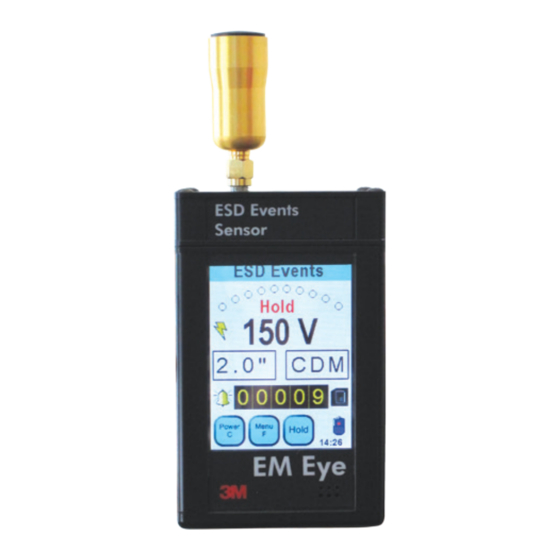
Page 13: Esd Events Sensor Display And Controls
ESD Events Sensor – Display and Controls For the detection of most ESD events using CDM, MM or HBM models. Settings and Displays (denotes a touch screen feature) Press the “Power C” button to: 1) Clear or reset the screen data (momentarily POWER C press) 2) Turn the meter OFF (long press for 4 seconds) - Page 14 EM Field Sensor – Display and Controls Settings and Displays (denotes a touch screen feature) Press the “Power C” button to: 1) Clear or reset the screen data (momentarily press) POWER C 2) Turn the meter OFF (long press for 4 seconds) Momentary press Long press adjusts time interval...
-
Page 15: Rf Signal Sensor Display And Controls
RF Signal Sensor – Display and Controls Settings and Displays (denotes a touch screen feature) Press the “Power C” button to: 1) Turn the meter ON (press the screen for three POWER C seconds) 2) Turn the meter OFF (press for three seconds) Momentary press Long press adjusts time interval... -
Page 16: Common Display And Controls
Common Display and Controls POWER and CLEAR The POWER C button turns off the EM Eye Meter CTM048 or ™ clears the values that are on display. To turn off the meter, press and hold the POWER C button for approximately four seconds or longer until the meter goes off. - Page 17 BATTERY The BATTERY symbol is not a touch feature. It displays the approximate level of battery life remaining for use. Full charge life. Half charge <1 hour charge, charging is required Battery is discharged, charging is required Charging in progress AUDIO INDICATORS The AUDIO INDICATOR button scrolls through the following audio modes: 1) Tone (bell)
-
Page 18: Esd Events Display And Controls
ESD Events Display and Controls MENU FUNCTION Press the MENU F icon and the NAVIGATOR icon appears. Press the up/down arrows to scroll through functions. Press the left or right arrows to set values and options. Press the center button to return to the main screen. Serial Number The serial number is a five-digit number indicated at the top left section of the screen. - Page 19 After pressing the triangle or the ALL-SIGNAL button, the lightning bolt symbols appears on the display. In this mode, the EM Eye Meter CTM048 will detect ESD events that are mostly CDM in nature. Not all events are captured and the information provided is based on proprietary algorithm which models and approximates for the event type.
- Page 20 Memory storage card The EM Eye Meter CTM048 works with microSD Cards. ™ Some cards may not be compatible. Non-compatibility is indicated by an “X” mark overlaid on the card button display. For other memory card types, please contact 3M for verification.
-
Page 21: Electromagnetic Field Sensor And Eirp Display And Controls
Electromagnetic Field Sensor, Power Density Meter and Effective Isotropically Radiated Power (EIRP) Meter Display and Controls MENU FUNCTION When the MENU F button is pressed momentarily, the INTERVAL and AVERAGE data recording timing can be configured. INTERVAL, in seconds, is the sampling time for PEAK data to be recorded onto the microSD storage card. - Page 22 EMF UNITS CONVERSION Pressing the UNITS button toggles between dBμV/m and V/m unit. POWER DENSITY UNITS The UNIT button is not a touch feature. The unit of power density is W/cm EIRP UNITS By pressing the distance area, the distance for EIRP measurements can be configured from 0.25 to 20 meters.
- Page 23 Reference mode is helpful if you wish to hear an audio alarm whenever EMF exceeds a certain level. If any of the reference modes are enabled, you should see the REF label shown on the main screen. The bottom line of the display will now show the reference value of the peak signal.
- Page 24 DATA STORAGE and READ (EM Field Sensor) The RECORD button (“R”) writes the displayed readings and settings onto the microSD ™ storage card; press the “R” button to activate RECORD. At this point, the button turns red and data is being written onto the storage card. To stop recording, press the red button again.
-
Page 25: Rf Signal Sensor Display And Controls
RF Signal Sensor Display and Controls MENU FUNCTION When the MENU F button is pressed momentarily, the INTERVAL and AVERAGE data recording timing can be configured. INTERVAL, in seconds, is the sampling time for PEAK data to be recorded onto the microSD storage card. - Page 26 Reference mode is helpful if you wish to hear an audio alarm whenever the RF exceeds a certain level. If any of the reference modes are enabled, you should see the REF label shown back in the main screen. The bottom line of the display will show the reference value of the peak signal.
-
Page 27: Access Data Using A Pc
To Access the Data Using a PC 1. Go to www.3Mstatic.com, click on Technical Info, Software Downloads to download the EM Eye File Converter software that will allow you to access the data from the 3M ™ Eye Meter CTM048 from your PC. -
Page 28: Calibration
Calibration The 3M EM Eye Meter CTM048 comes from the factory calibrated. It is ™ recommended that you calibrate the EM Eye Meter CTM048 once a year at the factory. Specifications GENERAL Audio Indicators Speaker: Beep or analog audio with selectable volume... - Page 29 CTM048-28 3M EM Eye Meter with EMI sensor, 80-0012-2093-0 CTM048-29 3M EM Eye Meter with RF sensor, 80-0012-2094-8 When sensors are added to a customer’s existing EM Eye Meter CTM048: CTC021 ESD sensor for use with the CTM048 EM Eye Meter, 80-0012-2095-5...
-
Page 30: Regulatory Information
Regulatory Information This equipment has been tested and found to comply with the limits for a Class A digital device, pursuant to Part 15 of the FCC Rules. These limits are designed to provide a reasonable protection against harmful interference when the equipment is operated in a commercial environment. -
Page 31: Warranty
3M’s option, to replace or repair the 3M product or refund the purchase price of the 3M product. Except where prohibited by law, 3M will not be liable for any indirect, special, incidental or consequential loss or damage arising from this 3M product, regardless of the legal theory asserted.
Need help?
Do you have a question about the CTM048 and is the answer not in the manual?
Questions and answers