Advertisement
Table of Contents
- 1 Table of Contents
- 2 WCVS Model Nomenclature
- 3 General Specification
- 4 General Information
- 5 Installation
- 6 Operation / Start-Up
- 7 Coil / Condenser Cleaning
- 8 Trouble Analysis Guide
- 9 Electrical Data
- 10 Electrical Wiring
- 11 Unit Dimensions
- 12 Wiring Diagram
- 13 Schematic Wiring Diagram
- Download this manual
Advertisement
Table of Contents

Related Manuals for Trane WCVS 270


Summary of Contents for Trane WCVS 270
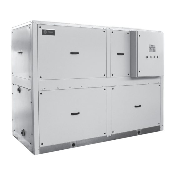
- Page 1 TRANE Installation Operation Maintenance Self Contained Water Cooled Air Conditioners Models WCVS 270, WCVS 330, WCVS 400, WCVS 470, WCVS 530, WCVS 600, WCVS 660, WCVS 730, WCVS 800, WCVS 900, WCVS 12H. WCVS-SVX01A-EN (Aug 2012)
- Page 3 Warranty is based on the general terms and conditions of Trane-Ingersoll This manual covers the installation, Rand. The warranty is void if the operation and maintenance of the Trane equipment is repaired or modified WCVS. without the written approval of the...
-
Page 4: Table Of Contents
TRANE ® Contents WCVS Model Nomenclature General Specification General Information Installation Operation / Start-up 7-10 Coil / Condenser Cleaning Trouble Analysis Guide Electrical Data Electrical Wiring Unit Dimensions 15-19 Wiring Diagram Schematic Wiring Diagram 21-25 (ii) -
Page 5: Wcvs Model Nomenclature
Factory Installed Options X = None DIGIT 12 Installed Motor kW O/Size MTR, Kw WCVS Models STD.MTR, Kw K = 5.5 WCVS 270 I = 3.7 DIGIT 13 L = 7.5 Refrigerent Type WCVS 330 I = 3.7 M = 11 WCVS 400 / 470 / 530 K = 5.5... -
Page 6: General Specification
® TRANE General Specification WCVS 270-12H... - Page 7 ® TRANE...
-
Page 8: General Information
Before preparing unit Trane-Ingersoll Rand urges all component for lifting, estimate the HVAC servicers working on Trane approximate centre of gravity for lifting The multiple-compressor WCVS units equipment, or any manufacturer’s safety. Due to the placement of internal consist of compressors, water-cooled... -
Page 9: Installation
® TRANE Installation Installation Vibration Isolation waterside piping. All field installed piping must conform to applicable local codes. Recommended piping For proper installation, consider the All units will be shipped with rubber- components is provided in figure 2, to following:... - Page 10 TRANE ® Installation - Condenser Water Pressure Drop Data WCVS 270 / 330 / 400 Condenser 25 T, Pressure Drop Vs GPM 11.3 10.3 WCVS 470 / 530 Condenser 35 T, Pressure Drop Vs GPM 10.0 22.31 21.31 20.31 19.31 18.31...
- Page 11 ® TRANE Installation - Condenser Water Pressure Drop Data WCVS 600 / 660 / 730 / 800 Condenser 50 T (Parallel) WPD Vs GPM 13.167 12.167 11.167 10.167 9.167 8.167 7.167 6.167 5.167 4.167 3.167 2.167 1.167 0.167 WCVS 900 / 12H Condenser Pressure Drop Vs GPM WCVS 900 &...
-
Page 12: Operation / Start-Up
TRANE ® Operation / Start-Up Start-up To Start Unit Note: Normal oil level on the manifolded compressors could be Before Start-up, confirm the following: 1. Turn on the unit power switch. any where from low to 3/4 . of the 1. - Page 13 ® TRANE Operation / Start-Up Weekly maintenance bolts, locking collars and sheaves. with a straight rod. Inspect, clean and tighten all * Relining condensers. Check the liquid line sight-glass. electrical connections. * Relining evaporator coils. Presence of bubbles indicates Inspect the TXV sensing bulbs for * Replacing evaporator coils.
- Page 14 TRANE ® Operation / Start-Up Figure 3-Typical Manifolded Circuit General Recommendations a flexible material such as heavy motor when installing ductwork. canvas. If a fire hazard exists, the Failure to do so may result in injury Cooling Towers recommended material is flexweave or death from entanglement in 1000, type FW-30 or equivalent.
- Page 15 ® TRANE Operation / Start-Up Figure 4 Fan / Duct Layout Comment R = 6 minimum Figure 5...
-
Page 16: Coil / Condenser Cleaning
Clean refrigerant coils with cold water should be engaged to determine what and detergent, or with one of the clamps. The end-plates must be treatment, if any, is advisable. Trane- centered when the clamp is commercially available chemical coil Ingersoll Rand warranty specifically cleaners. -
Page 17: Trouble Analysis Guide
® TRANE Trouble Analysis Guide POSSIBLE SYMPTOMS Hunting TXV Compr Amps HI/LO High sub - cooling Low sub-cooling Moisture indication HPCO Failure LPCO Failure Noisy compressor Suction line frosting Bubbles in sight Low Suction P High Suction P Low Discharge P... -
Page 18: Electrical Data
Model Power Supply LRA RLA LRA RLA LRA RLA FLA LRA Qty Size & MCB (ARI) (ARI) (ARI) (ARI) 380-415V/3Ph/50Hz 7.32 WCVS 270 14.4 14.4 Over-Size Fan Mtr---> 11.1 380-415V/3Ph/50Hz WCVS 330 7.32 17.8 17.8 Over-Size Fan Mtr---> 13.9 380-415V/3Ph/50Hz WCVS 400 11.1... -
Page 19: Electrical Wiring
Figure 7. terminal block against that in the wiring diagram. Should there be any inconsistency, please do not hesitate to contact the nearest Trane Sales & Service Office. LINE 1 & 2 TO BE CONNECTED IN SERIES WITH CONTROL. -
Page 20: Unit Dimensions
TRANE ® Unit Dimensions Water-Cooled Vertical System WCVS 270/330... - Page 21 ® TRANE Unit Dimensions Water-Cooled Vertical System WCVS 400/470...
- Page 22 TRANE ® Unit Dimensions Water-Cooled Vertical System WCVS 530/600/660...
- Page 23 ® TRANE Unit Dimensions Water-Cooled Vertical System WCVS 730/800...
- Page 24 TRANE ® Unit Dimensions Water-Cooled Vertical System WCVS 900-12H...
-
Page 25: Wiring Diagram
® TRANE Wiring Diagram (With Starter) WCVS 270/330... -
Page 26: Schematic Wiring Diagram
TRANE ® Schematic Wiring Diagram (With Starter) WCVS 400... - Page 27 ® TRANE Schematic Wiring Diagram (With Starter) WCVS 470/530...
- Page 28 TRANE ® Schematic Wiring Diagram (With Starter) WCVS 600/660 730/800...
- Page 29 ® TRANE Schematic Wiring Diagram (With Starter) WCVS 900...
- Page 30 TRANE ® Schematic Wiring Diagram (With Starter) WCVS 12H...
- Page 32 Stocking Location MALAYSIA www.trane.com Trane has a policy of continuous product and product data improvement and reserves the right to For more information, contact your local district change design and specifications without notice. Only qualified technicians should perform the installation office and servicing of equipment referred to in this publication.
Need help?
Do you have a question about the WCVS 270 and is the answer not in the manual?
Questions and answers