Trane Precedent WSJ150A Installation, Operation And Maintenance Manual
Packaged rooftop air conditioners
Hide thumbs
Also See for Precedent WSJ150A:
Table of Contents
Advertisement
Installation, Operation, and Maintenance
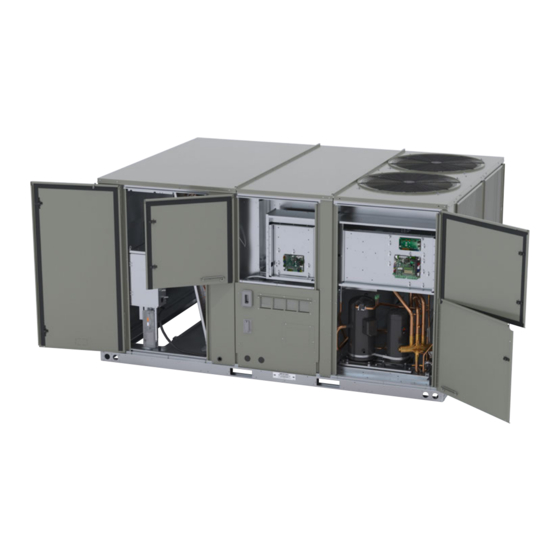
Packaged Rooftop Air
Conditioners
Precedent™ Heat Pump
Standard Efficiency
12.5 to 25 Tons — 60 Hz
Model Numbers: WSJ150A - WSJ300A
Only qualified personnel should install and service the equipment. The installation, starting up, and servicing of heating, ventilating, and air-conditioning equipment
can be hazardous and requires specific knowledge and training. Improperly installed, adjusted or altered equipment by an unqualified person could result in death or
serious injury. When working on the equipment, observe all precautions in the literature and on the tags, stickers, and labels that are attached to the equipment.
December 2022
SAFETY WARNING
PKGP-SVX010A-EN
Advertisement
Table of Contents


Need help?
Do you have a question about the Precedent WSJ150A and is the answer not in the manual?
Questions and answers