Table of Contents
Advertisement
Quick Links
Advertisement
Table of Contents
Troubleshooting

Related Manuals for mru OPTIMA


Summary of Contents for mru OPTIMA
- Page 1 OPTIMA USER MANUAL 4202EN-O...
- Page 2 USER MANUAL OPTIMA Producer: Legal notices / Intellectual property rights comments Original user manual © 2022 by MRU No part of this manual my be published in any form (print, fotocopy, electronic media or any other publication form) without a written approval by the publisher.
-
Page 3: Table Of Contents
USER MANUAL OPTIMA Table of contents Information for product and safety ..........7 1.1. Safety manual ....................7 1.2. Safety precautions ..................7 1.3. Ensure safety ....................8 1.4. Important general information (EN 50379 and VDI 4206) ..... 8 1.5. User guideline for rechargeable batteries ........9 Introduction .................. - Page 4 USER MANUAL OPTIMA Prepare measurement ..............36 6.1. Perform overall visual inspection ............36 6.2. Ensure power supply ................. 36 6.3. Automatic Auto-off function ..............36 6.4. Measuring with grid power supply / Battery charging ....36 6.5. Measurements in battery mode (battery monitoring) ....36 6.6.
- Page 5 USER MANUAL OPTIMA 7.11. Print measurement values ............... 62 Open menu print-out ..................62 Print measurement results with Speedprinter ......... 63 Print measurement results with Highspeed-Bluetooth- Thermoprinter ..................... 65 7.12. Stop measurement..................66 7.13. Last measured values ................66 Data storage ..................67 8.1.
- Page 6 USER MANUAL OPTIMA 11.4. Enter Cross section area ................88 11.5. Perform measurement ................88 Option: Monitoring flow rate ............ 90 Option: Auto-measurement ............91 Prefilter for high dust concentrations ........92 Appendix ..................94 15.1. Technical data ....................94 15.2.
-
Page 7: Information For Product And Safety
USER MANUAL OPTIMA Information for product and safety 1.1. Safety manual All general information and safety precautions of MRU products are listed in the supplied separate safety manual. Therefore, this manual must be read and observed before the first use of the instrument . -
Page 8: Ensure Safety
USER MANUAL OPTIMA 1.3. Ensure safety ► Please read the user manual completely before the first use. ► Only use the analyser for the intended use and within the parameters specified in the technical data. ► Do not use any violence. -
Page 9: User Guideline For Rechargeable Batteries
USER MANUAL OPTIMA • The use of the analyser for regulatory purposes is subject to special regulations (for example a periodical examination of the analyser). Please obtain the appropriate regulations from your local responsible authority. 1.5. User guideline for rechargeable batteries... -
Page 10: Introduction
USER MANUAL OPTIMA Introduction • This manual enables you to understand and safely operate this MRU Analyser. • Please read this manual with great vigilant and get familiar with the product before using it. • This Analyser may only be operated by competent personnel and for its intended use. -
Page 11: About Us
► Modifications or changes to the measuring device are not allowed. 2.2. About us The analyser is produced by the MRU GmbH in Neckarsulm, Germany (Founded in 1984), a medium sized company that specializes in devel- oping, producing and marketing high quality emission monitoring analysers. -
Page 12: Packaging
Hazardous waste must be returned to MRU prepaid. 2.5. Return of electronic equipment MRU is required to accept the return, for proper disposal, of all analys- ers delivered after 13th of August 2005. Analysers must be returned to MRU prepaid. -
Page 13: Description
Available options for this and other analysers can be found on the MRU Homepage or speak to a member of our sales team. 3.1. Gas flow diagram... -
Page 14: Analyser
USER MANUAL OPTIMA 3.2. Analyser The analyser consists of a compact and robust glass-fiber reinforced plastic housing. All connections relevant for the measurement are located on the bot- tom of the analyser. MRU GmbH, D-74172 Neckarsulm 14 / 110... -
Page 15: Condensate Seperator (Water Trap)
USER MANUAL OPTIMA Position Description Position Description Keypad Gas outlet Condensate separator Temperature connection T1 / T-Ambient air Display Temperature connection T2 / T-gas IR-Interface Connector AUX USB-Port / Charging port Sampling probe connec- tion Condensate separator SD-card reader (Only by... - Page 16 USER MANUAL OPTIMA Condensate separator without water stop filter Remove the condensate separator by lifting it out from the groove (1) of the analyser. Then pull out the condensate separator downwards (2). Liquid discharged from the condensate separator may be slightly acidic.
- Page 17 USER MANUAL OPTIMA Condensate separator without water stop filter MRU GmbH, D-74172 Neckarsulm 17 / 110...
- Page 18 USER MANUAL OPTIMA The water stop filter protects the analyser from moisture. The water stop filter closes as soon as there is a risk that condensate is sucked into the analyser. A closed water stop filter can be indicated, for example, by the fact that the flow rate is too low.
-
Page 19: Extraction Probes
USER MANUAL OPTIMA 3.4. Extraction probes In combination with the analyser, gas sampling probes are offered in different versions with fixed probe tube or with exchangeable probe tube. For a complete overview of accessories, see the company's current price list. -
Page 20: Operating
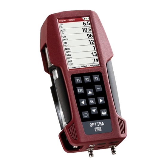
USER MANUAL OPTIMA Operating 4.1. Display All the information needed for the operation of the analyser can be ob- tained from the analyser's display, which contains the following infor- mation. Position Description Menu bar Display panel Menu Measurement values Function key bar... -
Page 21: Keypad
USER MANUAL OPTIMA 4.2. Keypad Description of the keys and their functions: Function A short press switches the analyser on without delay. ON/OFF Switching off the device is delayed to protect the sen- sor when no ambient air is present. Then purging is recommended before switching off. -
Page 22: Menu Structure
USER MANUAL OPTIMA 4.3. Menu structure The analyser organizes all available actions into three main menus: • Menu Measurement Here you will find all actions for the measuring tasks of the analyser. In particular, all installed measuring tasks are listed here and can be selected. -
Page 23: First Usage
USER MANUAL OPTIMA First usage After ensuring that the analyser is ready for operation, you can make some customer-specific adjustments during the initial startup. All settings can be changed at any time later. 5.1. Preparatory steps ► Unpack the analyser. - Page 24 USER MANUAL OPTIMA Setting Range Description LCD brightness 5 – 100 % Setting the display contrast Country Option By switching the country, the set O2 reference values are lost. The fuel list is reset. Country-specific de- fault settings and measur- ing procedures are also set.
-
Page 25: Export And Import Settings
USER MANUAL OPTIMA 5.3. Export and import settings You have the possibility to export saved settings to an SD card and im- port these settings to another analyser. Export user settings ► Make sure that there is an SD card in the analyser. -
Page 26: Import User Settings
USER MANUAL OPTIMA Import user settings ► Insert the SD card with the exported settings into the desired analyser. ► Go to the menu Settings. See also chapter 5.2 Customize settings, Page 23. ► Press the menu key. A selection list appears. - Page 27 USER MANUAL OPTIMA In the menu "Measurement settings" menu you can make the following customizations: Setting Range Description Temperature unit °C, °F Select temperature unit Diff. press. unit hPa/Pa, hPa, kPa/Pa, Select pressure unit kPa, mbar, mmH2O, cmH20, inchH2O, mmHG,...
-
Page 28: Set Bluetooth Parameters
USER MANUAL OPTIMA 5.5. Set Bluetooth parameters Depending on the features, the analyser can be used to exchange meas- urement data wirelessly with external devices: • With MRU4U (App for Android and iOS Smartphones) • With MRU4Win • With MRU Bluetooth-Printer... -
Page 29: Setting Date And Time
USER MANUAL OPTIMA 5.6. Setting date and time If the built-in rechargeable battery is completely discharged, a new setting of these values is required ► Press F3. The Extra menu appears. ► Select Date / Time. ► Press OK. -
Page 30: Set Co-Limit
USER MANUAL OPTIMA 5.8. Set CO-Limit ► Select Gas measurements. ► Press OK. The menu Selection meas. program appears. ► Select the desired measuring program from which the CO limit value is to be set ► Press F1. The menu Co-Limit appears. -
Page 31: Select Fuel Types And O Reference
USER MANUAL OPTIMA 5.10. Select fuel types and O reference NOTE Note that you can only select the Fuel type selection if the combustion calculation has been switched on. See also chapter 5.4 Set measurement, Page 26 Each time a measuring program for flue gas measurement is called up, a fuel can be selected from a list. -
Page 32: Set O2-Reference
USER MANUAL OPTIMA Set O2-reference ► Go the menu Fuel type list. See also chapter Add fuels to fuel type selection, Page 31. ► Select the desired fuel. ► Press F3. The menu Info fuel type appears. ► Stellen Sie den gewünschten O2-Bezug ein. - Page 33 USER MANUAL OPTIMA NOTE The last 4 fuels in the menu Fuel type list are the user fuels. The user fuels are indicated in the menu Fuel Type list in green colour. ► Go the menu Fuel type list. See also chapter Add fuels to fuel type selection, Page 31.
-
Page 34: Define Measurement Window
USER MANUAL OPTIMA ► Select the desired fuel parameter. ► Change the desired fuel parameter. ► Press OK. The defined user fuel appears in the menu Fuel type list. You can add the defined user fuel to the menu Fuel type selec- tion. -
Page 35: Configure Zoom Window
USER MANUAL OPTIMA 5.13. Configure zoom window In each measuring program, a zoom window is available for the en- larged display of measured values. You can choose between two zoom views. ► Press the arrow key at the top to display four measured values with the respective curve. -
Page 36: Prepare Measurement
6.2. Ensure power supply The analyser can be used with: • with the internal MRU battery (provided) • with the MRU battery charger (provided) External equipment may only be connected while the analyser is switched off! 6.3. -
Page 37: Operating Temperature
USER MANUAL OPTIMA 6.6. Operating temperature If the analyser has been stored at low temperatures, it will require some time to equilibrate to the ambient temperature before being switched on. If it does not equilibrate, condensation will occur inside the analyser! -
Page 38: Automatic Zero Point
USER MANUAL OPTIMA 6.9. Automatic zero point NOTE The probe must not be in the exhaust gas during the zeroing. ► Switch on the analyser. The analyser autonomously carries out a zero-point measurement. During zeroing, the -> 0.0 <- symbol flashes in the upper right corner of the display. -
Page 39: Performing Measurement
USER MANUAL OPTIMA Performing measurement In the basic configuration, each analyser has the complete functionality you need for gas measurement. The process of gas measurement is described below. The description of other optionally available measuring programs can be found in the appendix or on separate supplementary sheets. -
Page 40: Select Measurement Program
USER MANUAL OPTIMA Positioning the probe in the core flow: Insert the probe pipe slowly into the stack and position your probe pipe when you have reached the maximum flue gas temperature that is dis- played. Maximum temperature has been reached when the arrows (left picture) disappear, max. - Page 41 USER MANUAL OPTIMA ► Go to the Measurement menu. ► Select Gas measurements. ► Press OK. The menu Selection meas. program appears. ► Select the desired measurement program. ► If necessary, change the CO-Limit. See also chapter 5.8 Set CO-Limit, Page 30.
-
Page 42: Measurement Window
USER MANUAL OPTIMA Measurement window The measured values are organised in three windows of 7 measured val- ues each. Which measured value is displayed at which position in the window is configurable. See also Chapter 5.12, Page 34 and chapter 5.13Configure zoom window, Page 35. -
Page 43: Performing Measurements With Measurement Assistant
USER MANUAL OPTIMA 7.2. Performing measurements with measurement assistant With the help of the measurement assistant, you can collect several in- dividual measurements. You can export the collected measurements via Bluetooth or QR code to the app MRU4u (or other management pro- grammes) and/or print them out. -
Page 44: Collect Measurement
USER MANUAL OPTIMA ► Go to the Measurement menu. ► Press OK. The menu Selection meas. program appears. ► Press the menu key. A selection list appears. ► Select the desired template. ► Press OK. The menu changes accordingly. - Page 45 USER MANUAL OPTIMA NOTE Users who start with the Annular-gap test first can se- lect a fuel when selecting the Annular-gap test. This fuel is then also used for the following measurements (e.g. Program 2, Program 1). See also chapter Add fuels to fuel type selection, Page 31.
-
Page 46: Reset Collected Measurements
USER MANUAL OPTIMA ► Select Program 1. ► Press OK. If activated, the core flow search appears. ► Perform the core flow search and then press F1. See also chapter Core flow search, Page 39. ► Press F2, after you have performed the measurement. -
Page 47: Print Collected Measurements
USER MANUAL OPTIMA NOTE You can also reset the collected measurements directly via the function key bar. ► Press F3. A message appears. Print collected measurements Before printing the collected measurements, you have the possibility to display a print preview. -
Page 48: Individualise Function Key F2
USER MANUAL OPTIMA Individualise function key F2 Before you can export the collected measurements via QR code or Blue- tooth or save them in the data memory, you must individualise the function key F2. ► Press the context menu. A selection list appears. -
Page 49: Transmitting Measurements To Mru4U
USER MANUAL OPTIMA NOTE If you set Bluetooth to F2 "If re- quired", measurement data will al- ways be transmitted to MRU4u as soon as there is a connection be- tween the analyser and MRU4u. The display in the measurement as-... -
Page 50: Transmitting Measurements To Mru4U Via Qr Code
USER MANUAL OPTIMA Transmitting measurements to MRU4u via QR code Before you can transmit measurements to MRU4u via Bluetooth, you must adjust the F2 function key accordingly. ► Open the menu Setting assist. See also chapter Individualise function key F2, Page 48. -
Page 51: Store Measurements
USER MANUAL OPTIMA ► Press F2. The QR-Code appears. ► Scan the QR-Code with MRU4u. Store measurements Before you can transmit measurements to MRU4u via Bluetooth, you must adjust the F2 function key accordingly. ► Open the menu Setting assist. -
Page 52: Send Messages As E-Mail
USER MANUAL OPTIMA Send messages as E-Mail You have the possibility to scan the measurements by OR code and send them as an e-mail. ► Press the menu key. A selection list appears. ► Select Send Mail …(QR). ► Press OK. -
Page 53: Store Values Into Temporary Buffer
USER MANUAL OPTIMA Store values into temporary buffer During a running measurement you can store the store the current val- ues in the temporary memory. ► Start a Gas measurement. See also chapter 7.1 Perform Gas measurement, Page 39. - Page 54 USER MANUAL OPTIMA ► Stop the Measurement. The measuring window is greyed out. ► Press F3. The measured values stored in the temporary memory are dis- played. If you have stopped a measurement without first storing the measured values in the temporary buffer, you can store the measured values directly in the temporary buffer from the function key bar.
-
Page 55: Overwrite Measured Values In Temporary Buffer
USER MANUAL OPTIMA Overwrite measured values in temporary buffer You can overwrite the measured values stored in the temporary buffer with the currently displayed measured values ► Press the menu key. A selection list appears. ► Select overwrite clipboard. -
Page 56: Perform Annular-Gap Test
► Press F3. The currently measured values for Draft and T-gap are displayed. The MRU annular gap multi-hole probe No. 56352 is suitable for annu- lar gap measurement. The silicone hose is attached to the condensate separator of the analyser. -
Page 57: Perform Test Program
USER MANUAL OPTIMA 7.5. Perform Test program The test program is used by test facilities to check the analyser by means of test gas in the measuring program. No calculations are performed during the test program. ► Select Gas Measurements. -
Page 58: Perform Pressure Measurement
USER MANUAL OPTIMA The user can freeze the draft data by means of the F3 key “hold draft”. The frozen data is displayed in green. The unfreeze the measurement one has to exit the menu and enter again All other measurements are processed continuously independent of the draft measurement status. -
Page 59: Perform Differential Temperature Measurement
► Plug a temperature sensor into the T2 connection. NOTE The accuracy of the difference temperature measure- ment is guaranteed only on use of the MRU tempera- ture sensors. ► Go to the Measurement menu. ► Select Diff. Temp. measurement. -
Page 60: Store Measurement Values
USER MANUAL OPTIMA ► Press the menu key. A selection list appears. ► Select the desired item from the selection list. For example, select the print-out (Pr) item to print the measurement. 7.10. Store measurement values If "store" is displayed in the function key bar, you can save measure-... -
Page 61: Enter T-Boiler, Soot And Derivative
USER MANUAL OPTIMA Enter T-boiler, Soot and Derivative The analyser does not have a soot measurement. ► However, you can enter determined soot data to save or print them together with the measurement data. NOTE Before you can enter the soot data, you have to acti- vate the setting “Add soot &... -
Page 62: Print Measurement Values
USER MANUAL OPTIMA 7.11. Print measurement values You have the possibility to print measurement results via the following optionally available printers. • Speed printer (IR desktop printer) • HSP 580 (Highspeed-Bluetooth-Thermoprinter) NOTE Before you can print measurement results, you must select and configure the appropriate printer (printer type) in the menu printout. -
Page 63: Print Measurement Results With Speedprinter
USER MANUAL OPTIMA Setting Description Printer type Selection of the printer type Print site lines Line 1 (plant number) is required. The other lines (free text lines) can be printed if required. Print analyser info Measurement printouts can be made shorter by omitting the analyser. - Page 64 USER MANUAL OPTIMA ► Press the printer key. Optionally, press the context menu key and se- lect Printout (Pr.) A print-out is created. Further technical specifications as well as battery and paper rolls changes please see separate printer manual.
-
Page 65: Print Measurement Results With Highspeed-Bluetooth-Thermoprinter
USER MANUAL OPTIMA Print measurement results with Highspeed-Bluetooth-Thermoprinter ► Go to the menu print-out. See also chapter Open menu print-out, Page 62. ► Select Bluetooth-HSP as Printer type. ► Press F2. The connection between analyser and the printer is established. -
Page 66: Stop Measurement
USER MANUAL OPTIMA 7.12. Stop measurement A running measurement can be stopped at any time by pressing the F1 key. The window changes colour and the measured values are frozen. All measured values available at the time of stopping are available in the ana- lyser and can still be displayed. -
Page 67: Data Storage
USER MANUAL OPTIMA Data storage 8.1. Organize data storage The basis for the data storage of the analyser is saved sets of sites inside the analyser. Each site has a distinct site number as well as 8 additional free text lines for names and address. -
Page 68: Sites Administration
USER MANUAL OPTIMA Das Menü Speicher Info erscheint. The menu Memory info appears. Information about the data storage is listed. 8.3. Sites administration In the sub menu Sites administration, you can: Im Menüpunkt Anlagenstamm können Sie • View all data of the stored sites •... -
Page 69: View Sites
USER MANUAL OPTIMA View sites ► Go to the Storage menu. ► Select Sites administration. The menu Sites administration appears. Each stored site is displayed on a page with the colored site num- ber and eight additional free text lines. -
Page 70: Delete Sites
USER MANUAL OPTIMA Delete sites You can delete sites individually or delete all sites simultaneously Delete sites individually ► Go to the Storage menu. ► Select Sites administration. ► Press OK. The menu Sites administration appears. ► Select the site you want to delete. -
Page 71: Transfer Data Via Using Sd Card
USER MANUAL OPTIMA Delete all sites ► Go to the Storage menu. ► Select Delete all sites. ► Press OK. A message appears. ► Select continue to delete all sites. ► Select abort to retain all sites. ► Press OK. -
Page 72: Import Sites
USER MANUAL OPTIMA Import sites With this function you can import Sites which have been created on a computer or another Analyser. The File name must have the name “anlagen.csv“(anlagen = German for sites). The file has no column heading that means that the first line al- ready has user data. -
Page 73: Export Sites
USER MANUAL OPTIMA Export sites This function can be used for an analyser back up or if you wish to sup-ply the analyser information to a computer program or another ana-lyser. This is very handy if you have made some modifications inside the analyser... -
Page 74: Export Measurements
USER MANUAL OPTIMA Export measurements With this function, the analyser can make its stored measurements avail- able to a PC. Attention, this function is not suitable as a backup or for transferring the measurements to other measuring devices, as the measurements cannot be imported again. -
Page 75: Measurements In Data Storage
USER MANUAL OPTIMA 8.5. Measurements in Data storage View measurements ► Go to the Storage menu. ► Select View measurements. The menu View measurements appears. An overview of the number of stored measurements depending on the measurement type appears. -
Page 76: Delete Measurements
USER MANUAL OPTIMA Delete measurements You can • Delete single measurements • Delete all measurements or delete all measurements of a measure- ment type Delete single measurements ► Go to the Storage menu. ► Select View measurements. ► Drücken Sie OK. - Page 77 USER MANUAL OPTIMA Delete all measurements ► Go to the Storage menu. ► Select Delete measurements. ► Press OK. The menu Delete measurements appears. ► Select which measurement type you want to delete. ► Press F2. A message appears.
-
Page 78: Extras / Adjustment
The Service menu is protected by a PIN code against unauthorized access. For the PIN code, contact an MRU service center (www.mru.eu). If you have started the PIN code query by mistake, press the ESC key. You will return to the Extras menu. -
Page 79: Default Settings
USER MANUAL OPTIMA 9.2. Default settings The analyser is reset to the default settings. NOTE With the default settings, all individual settings are lost. ► Go to the Extras menu. ► Select Default settings. ► Press OK. A window appears. -
Page 80: Service Values
In this menu you will see all ser- vice values of the sensors and also other parameters. In case of a defect contact the MRU service department. The MRU ser-vice technician will ask you about these values or he will ask you to send them by fax or email. -
Page 81: Performing Leak Test
USER MANUAL OPTIMA NOTE For the PIN code, contact an MRU service center (www.mru.eu) ► Enter the Pin-Code. The selected function test is switched on or off. 9.4. Performing leak test During the leak test, the system (including the condensate separator) is checked for leaks by the analyser. -
Page 82: Contents Sd Card
If the leak proof test is not passed, you must check the probe including the tubing and the condensate separator. If no leakage is detected on these external parts, the analyser has to be check service center (service centers at www.mru.eu). 9.5. Contents SD card ► Go to the Extras menu. -
Page 83: Device Info
USER MANUAL OPTIMA 9.6. Device info ► Go to the Extras menu. ► Select Device info. ► Press OK. The menu Device info appears. Information about the analyser is displayed, for example serial number and firmware version. Options list ►... -
Page 84: Maintenance And Care
The next time you switch on, you will again be reminded to carry out the annual service. A complete check at an MRU service centre (MRU service centres can be found at www.mru.eu) includes the function check and calibration or... -
Page 85: Option Gas Flow Measurement
USER MANUAL OPTIMA 11 Option Gas flow measurement This option enables the measurement of the flow velocity in flue pipes or flue gas stacks 11.1. Connect Prandtl (Pitot) tube to analyser MRU GmbH, D-74172 Neckarsulm 85 / 110... -
Page 86: Open Menu Gas Flow Measurement
USER MANUAL OPTIMA 11.2. Open menu Gas flow measurement ► Go to the Measurement menu. ► Select Gas flow measurement. ► Press OK. The menu Gas flow measurement appears. NOTE If you have not connected a temperature sensor, the... -
Page 87: Define Settings And Parameters
USER MANUAL OPTIMA 11.3. Define settings and parameters ► Press F1. The menu Settings appear. ► Setup the desired measurement units. ► Set the desired parameter. ► Select Gas composition (OK) to adjust the gas composition to your needs. -
Page 88: Enter Cross Section Area
USER MANUAL OPTIMA 11.4. Enter Cross section area NOTE Before you can perform a flow measurement, you must select the desired cross-section and enter the corre- sponding side length ► Press the arrow keys left/right in the menu Gas flow measurement. - Page 89 USER MANUAL OPTIMA Legend: P stat << P baro v = flow velocity [m/s] P baro = Barometric pressure [hPa] T = gas temperature P stat = Static pressure [Pa] P dyn. = Dynamic pressure [Pa] ► Press F2 as soon as the measurement for measuring point no. 1 is fin- ished.
-
Page 90: Option: Monitoring Flow Rate
USER MANUAL OPTIMA 12 Option: Monitoring flow rate The flow rate is continuously monitored. In the event of an error, the following message appears in the display: If the flow rate is too low, this message is displayed every 8 seconds. -
Page 91: Option: Auto-Measurement
USER MANUAL OPTIMA 13 Option: Auto-measurement With the automatic measurement option, the analyser can log continu- ous measurements independently. You can largely adapt the properties of the automatic measurement to your individual requirements. The data is stored in the internal data memory and can then be transferred to the SD card. -
Page 92: Prefilter For High Dust Concentrations
USER MANUAL OPTIMA NOTE Setting Average values: Yes: Analyser calculates the mean during each interval and stores this value. No: Analyser stores the values being measured at the end of the interval. ► Press F1. The measurement starts. The display shows the remaining time of the measurement. - Page 93 USER MANUAL OPTIMA ► Pull the hose line (gas line) out of the probe handle. ► Shorten the hose line (gas line) by approx. 9 cm. ► Insert the pre-filter between the hose line (gas line) and the probe handle.
-
Page 94: Appendix
USER MANUAL OPTIMA 15 Appendix 15.1. Technical data General data Operating temperature +5°C … +45 °C / +41°F … +113 °F Rel. Humidity, non-condensing Storage Temperature -20°C - +50°C / -4°F … 122° F Internal Battery Pack, operating hours (typical) Li-Ion, 20h Power supply 100 - 240 V / 5V DC / 1.200... - Page 95 USER MANUAL OPTIMA (requires recovery time of double the exposure time for CO > 20 Vol%) Electrochemical Sensor Measuring range extension up to 25% (Option #62414) Measuring Range 0..25 Vol% Resolution 0,1 % Abs. Accuracy ± 0,2 Vol.% Response Time T90 <20s...
- Page 96 USER MANUAL OPTIMA Electrochemical Sensor NO (Option #63058) Nom. Measuring Range 0 – 1000 ppm Overload Range < 5000 ppm Resolution 1 ppm Accuracy abs./reading ± 5ppm 5% (0 – 1000 ppm) 10% (> 1000 ppm) Response Time T90 < 30s...
- Page 97 Number of thermocouple type K input Measuring Range -40 °C - 1200 °C Accuracy abs. / reading ±2°C/ 0,5% Flue gas temperature (using MRU probe) Measuring Range with high grade steel 0 - 800°C probe pipe Measuring range with Inconel probe pipe 0 - 1100°C Accuracy abs.
- Page 98 USER MANUAL OPTIMA Accuracy abs. / reading 0,02 hPa / Differential Pressure Measuring Range ± 100 hPa Accuracy abs. / reading 0,02 hPa oder 1% Calculated values Measuring range (fuel type dependant) 0 - CO Accuracy abs. ± 0,3 Vol. %...
-
Page 99: Analysis And Calculation
USER MANUAL OPTIMA 15.2. Analysis and calculation Continuous conversions to NO [ ppm ] related to. on 0% rest O (undiluted) [ ppm ] related to. on fuel type dependent O reference value [ mg/m [ mg/kWh] [ mg/MJ] [ mg/m... -
Page 100: Reset Analyser
USER MANUAL OPTIMA Measured values Unit [ppm] [ppm] [ppm] [ppm] Temp. Ambient air (Thermo-Element) [°C] [°F] Temp. Flue gas (Thermo-Element) [°C] [°F] [ppm] Draft [hPa] Further continuously calculated measured values Unit Efficiency ETA Efficiency ETA condensed Losses Losses condensed Lambda Dew point [°C] [°F]... -
Page 101: Troubleshooting
USER MANUAL OPTIMA 15.4. Troubleshooting Troubleshooting on the analyser Effect Error Cause Solution indication Analyser does Device does not react on Press ESC and not respond any key. Power-ON but- to any key tons at the simul- touch taneously. Undercooling Display indica- e.g. -
Page 102: Troubleshooting Condensate Separator
USER MANUAL OPTIMA Troubleshooting condensate separator 1. Effect 2. Cause 3. Solution Dirt and / or humidity in- Fine filters are wet and / Check filters more side the device or dirty. often No filter effects Renew them if Sensor failure... -
Page 103: Update Firmware
USER MANUAL OPTIMA 15.5. Update firmware Check current firmware version ► Go to the Extras menu. ► Select Device info. The menu Device info appears. The current firmware version appears. In this example, the firm- ware version is 3.00.02. -
Page 104: Check New Firmware Version
USER MANUAL OPTIMA ► Select install firmware. ► Press OK. The update is performed. After the update has been performed, a message appears. ► Confirm the message with OK. ► Switch the analyser off again after the successful update. - Page 105 USER MANUAL OPTIMA ► Go to the Extras menu. ► Select Device info. ► Press OK. The menu Device info appears. The new Firmware version is displayed. ► Repeat the update process if the old firmware version is still dis- played.
-
Page 106: Display Your Own Logo
USER MANUAL OPTIMA 15.6. Display your own logo You have the option of importing your own start logo into the analyser and having it displayed when you switch the analyser on. Create your own logo ► Create your own logo. - Page 107 USER MANUAL OPTIMA ► Save your logo to an SD card with the file name logo4u.jpg. NOTE Pay attention to the file format jpg when saving/ex- porting. If you use a graphics program other than MS Paint, you must disable the following items before exporting.
-
Page 108: Import Logo Into Analyser
USER MANUAL OPTIMA Import logo into analyser ► Go to the to the menu Settings. 5.2 Customize settings, Page 23. ► Insert the SD card with the logo4u.jpg file into the analyser. A message appears. The logo is saved. -
Page 109: Declaration Of Conformity
USER MANUAL OPTIMA 16 Declaration of conformity MRU GmbH, D-74172 Neckarsulm 109 / 110...
Need help?
Do you have a question about the OPTIMA and is the answer not in the manual?
Questions and answers