Table of Contents
Advertisement
Quick Links
78813034408-B Manual Instruction, 945DSP
Print this document 74% full size to fit in 945DSP carrying bag!
Overall size of document, with binding must not exceed 170mm high x 100mm wide.
Revision History
Rev 6
Released to art department
12/1/2000
Removed prior version screen image from page 13 and 17
12/12/2000
Page 5 – added reference to speaker disabled on low power
Released to Art Department
12/20/2000
Changed dbrn0P noise limits
Increased font size to 12pn
Rev 8
Resent to art department
Changed screen label graphics to permit pdf printing
Changed warning re effects of leakage current on opens P11
Added statement that escape key cancels P21
Changed shutdown beeps from 10 to 6 on P5
Rev B
Version 2.15 Changes
2004/03/08
Removed Ohms to Distance, restored Soak
Advertisement
Table of Contents

Related Manuals for 3M Dynatel 945DSP


Summary of Contents for 3M Dynatel 945DSP
- Page 1 78813034408-B Manual Instruction, 945DSP Print this document 74% full size to fit in 945DSP carrying bag! Overall size of document, with binding must not exceed 170mm high x 100mm wide. Revision History Rev 6 Released to art department 12/1/2000 Removed prior version screen image from page 13 and 17 12/12/2000 Page 5 –...
- Page 2 Dynatel 945DSP Subscriber Loop Tester Instruction Manual March 8, 2004 78-8130-3440-8 Rev. B...
- Page 3 Equipment EN 300 386 V1.2.1 ( 1998-11) – EMC for Telecommunications Equipment The Products Covered by this Declaration 3M Dynatel 945DSP Subscriber Loop Tester The Basis on which Conformity is being Declared The product identified above complies with the requirements of the above EU...
-
Page 4: Table Of Contents
Table of Contents POWER ON SCREEN ..........6 VOLTAGE TEST ............ 7 LOOP CURRENT ........... 8 GROUND RESISTANCE ......... 9 RINGERS COUNT.......... 10 RESISTANCE............11 INSULATION SOAK........12 OPENS FAULT LOCATOR ........ 13 OPENS SETUP ..........14 SEND TONE ............16 LOAD COIL COUNT ........ - Page 5 For Warranty, Repair or Ordering Information, please refer to these sections near the end of this manual. The Dynatel 945DSP comes with a carrying case and should remain in the case to give extra protection from shock and the environment. Install the unit in the case by sliding it under the upper flap and securing it at the bottom with the elastic strap.
- Page 6 Batteries A set of four “AA” alkaline batteries are provided. To install them in the unit, loosen the two screws on the battery cover and follow the placement diagram in the bottom of the battery compartment. The unit will operate for about 25 hours of continuous use ( no backlite ) on a fresh set of alkaline batteries.
- Page 7 thinner borders indicate stored results. When more than one result is shown on the screen, cycles between them. The index at the end of this manual is a good way to quickly find the meaning of any icon. Also, on the inside pouch of the carrying case there is a card which provides an easy reference to the most common of the graphical icons.
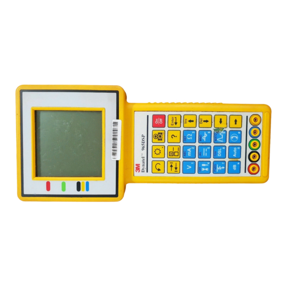
- Page 8 Keypad The 945DSP Keypad has twenty keys. The twelve blue keys are dual purpose. In some tests they function as numeric keys, but most of the time they are used to select a test. Page 4...
- Page 9 Control Keys On/Reset/Off - Turns on the unit, or if it is already on, resets to the power on screen. Press again to switch off. Adjusts the speaker volume. Toggles the backlite on and off Chooses an option or selects measurement mode - T or R or G.
-
Page 10: Power On Screen
Power On Screen Regional Settings - line frequency, units and auto shut-off This is the screen that you see when you first turn on the 945DSP. It shows the copyright year and the software version. The battery symbol on the right gives an indication of the approximate battery level. - Page 11 Then press the desired test or control key. Page 7...
-
Page 12: Voltage Test
Voltage Test Selects T-R or R-G or T-G Selects AC or DC measurements This function measures the DC or AC voltage between the test leads. The test begins by displaying the voltage from the Red to Black lead in the center box. This box has a thicker border than the others indicating that this reading is ‘live’... -
Page 13: Loop Current
Loop Current Runs the ground resistance test. Runs a ringers count. This function measures the DC current flowing through a 430 Ohm resistor inside the 945DSP. The test is run on a working pair. Connect the Red and Black leads and press to measure loop current. -
Page 14: Ground Resistance
Ground Resistance Reruns the ground resistance test. You reach Ground Resistance from the mA screen. This test measures the resistance of the ground between a Central Office (C.O.) and the 945DSP by using an active pair. Ground Resistance must be done on a working POTS circuit. -
Page 15: Ringers Count
Ringers Count Count again. Use this test to verify the connectivity into a subscriber’s premise or to look for abandoned lines left bridged on. First, disconnect the line towards the CO and connect the clips to the pair going toward the subscriber. Press verify the loop current as 0mA ( the CO is disconnected ). -
Page 16: Resistance
Resistance Selects T-R or R-G or T-G Runs the soak test. This function measures the leakage resistance between the test leads. The test begins by displaying the resistance from the Red to Black lead in the center box. This box has a thicker border than the others indicating that this reading is ‘live’... -
Page 17: Insulation Soak
Insulation Soak Selects R-G or T-G Saves the reference reading This function monitors the leakage resistance from the test leads to ground and indicates changes in the insulation resistance while it is stressed with a high voltage over time. The test begins by displaying the insulation resistance of the Red lead in the upper left box. -
Page 18: Opens Fault Locator
Opens Fault Locator Ring Length Mutual Tip Length Selects T-R or R-G or T-G Setup capacitance factors The opens function can be used to determine the distance to both a “full” open as well as to a “partial” open. There are three measurements provided –... -
Page 19: Opens Setup
Note: The tip-ground and ring-ground measurements require that the green lead be connected to a good ground. All of these measurements depend on the 945DSP knowing the capacitance per length of cable. Press to enter this value for the cable type in use. See the next section for more details. - Page 20 settings the capacitance factors should be entered in nF/km, otherwise use uF/mile. Here are the factors for several typical cable types: uF/Mile nF / Km Groun Mutu Groun Mutu Aircore 0.125 0.083 77.7 51.6 Jelly 0.140 0.083 87.0 51.6 Filled 2 Pair 0.155 0.083...
-
Page 21: Send Tone
Send Tone Selects 404,1004,2804Hz or 577Hz Trace Tone Adjusts speaker volume. Counts load coils. This function sends a tone on a pair for loss testing or pair identification. Use the key to select the desired tone. There are three precision tones – 404Hz, 1004Hz and 2804Hz and a 577Hz ID tone. -
Page 22: Load Coil Count
Load Coil Count To count load coils, press to open the send tone screen and then press to reach the load coil counter. This function counts up to five load coils on an unterminated pair. The load coil count can take several minutes to complete. -
Page 23: Dialing
Dialing Selects off-hook or on-hook Selects tone or pulse dialing Use the blue keys for dialing. Use the autodialer. Adjusts speaker volume. Press dB to begin testing. Use this function to test the functionality of the line or to dial a test line before running a loss or noise test. Press to reach this screen, then press again to go offhook. -
Page 24: Autodialer
Autodialer selects a stored number A-J goes off hook and dials the stored number Use the blue keys to change a stored a number. stores the new number backs up to make corrections The autodialer stores up to 10 frequently used phone numbers. -
Page 25: Loss
Loss Level Frequency Selects Loss, Noise, or Adjusts speaker volume. Note that the key runs loss, noise and longitudinal balance. You may have to press dB more than once to cycle the loss screen into view. Use this function to measure loss from the far-end to near- end using a tone between 200 Hz and 5 kHz. -
Page 26: Noise And Power Influence
Noise and Power Influence Power Influence Noise PI Noise = Computed Balance Selects Loss, Noise, or Toggles between noise and power influence Adjusts speaker volume. Note that the key runs loss, noise and longitudinal balance. You may have to press dB more than once to cycle the combined noise and power influence screen into view. -
Page 27: Longitudinal Balance
Longitudinal Balance Selects Loss, Noise, or Note that the key runs loss, noise and longitudinal balance. You may have to press dB more than once to cycle the longitudinal balance screen into view. Use this function to display the longitudinal balance of the pair. -
Page 28: Self Calibration
Self Calibration Use this function to calibrate the 945DSP anytime the outside temperature changes by more than 35°F (20°C). Calibrate the 945DSP at the same temperature at which it will be used. Short the red, green, and black leads together then press You will see the following screen while the calibration is in progress. -
Page 29: Regional Settings
Regional Settings Chooses an option (i.e. M or ft) Selects M/ft, auto-off, 60/50Hz To reach the regional settings screen, turn on the unit and press . Use the key to choose an option and the key to move to the next selection screen. Press when you are finished or to cancel. -
Page 30: Typical Measurements On A Pots Line
80 to 90 > 90 dBrnC <-10 -10 to 0 > 0 dBm0p Ground Res. * < 25 > 25 Ohms Insulation Res.> 3M 3k to 3M < 3k Ohms Balance. >59 50 to 59 < 50 dB * Note: Ground Resistance can not be measured on “floating tip”... -
Page 31: Warranty
3M Telecom Repair Service at: USA: 1-800-426-8688 Canada: 1-800-265-6027 or call your local 3M representative in other countries for further details on repair service. Warranty New Product Limited Warranty: 3M Telecom Systems (herein referred to as the... - Page 32 Limit of Liability: In no event will 3M or Seller be responsible or liable for special, incidental, or consequential losses or damages, whether based in tort or contract. Fulfillment of 3M’s warranty obligations will be Customer’s exclusive remedy...
- Page 33 Important Purchaser Notice All statements, recommendations, and technical information related to Seller’s products are based on information believed to be reliable, but the accuracy or completeness thereof is not guaranteed. Before using the equipment, the buyer should determine the suitability of the product for the intended use, and assumes all risk and liability whatsoever in connection with that use.
-
Page 34: Index To Symbols
Index to Symbols Indicates the Ring or B lead - P 3 Indicates the Ground or Earth lead- P 3 Indicates the Tip or A lead- P 3 On/Reset/Off - Press once for on, again for off. P Adjusts the speaker volume. P. 18 Toggles the backlite on and off P. - Page 35 Low voltage warning – change the batteries. P. 6 Voltage Test P. 7 Key selects AC or DC in Volts Test P. 7 P. 7 P. 7 Loop current in milliamps P.Error! Bookmark not defined. In mA, runs the ground resistance test. P. 9 Ground Resistance P.
- Page 36 Telecom Systems Division 6801 River Place Blvd. Austin, Texas 78726-9000 USA http://www.mmm.com/telecom 3M 2000...
Need help?
Do you have a question about the Dynatel 945DSP and is the answer not in the manual?
Questions and answers