
Related Manuals for 3M Dynatel 2273ME Series


Summary of Contents for 3M Dynatel 2273ME Series
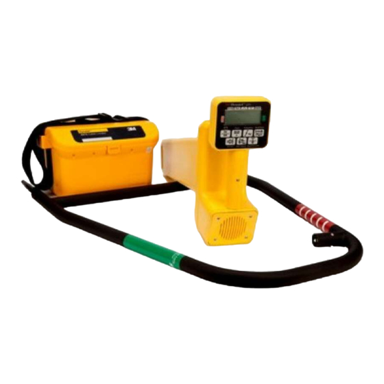
- Page 1 Dynatel ™ ™ Cable/Pipe/Fault Advanced Locator 2250ME/2273ME Series (With 3-watt, 5-watt, or 12-watt Transmitter) Operator’s Manual 2250ME 2250ME-iD 2273ME 2273ME-iD February 2009 78-8130-6151-8-E...
-
Page 2: Table Of Contents
Depth and Current Estimate ................20 Frequencies ......................21 Locating in Directional Peak Mode ..............22 Locating Active Duct Probes (Sondes) ............... 25 Buried Sheath Faults And Earth/Return Faults ........... 26 Electronic Markers and 3M EMS iD Markers ......... 28 ™ ™ Locating 3M EMS Markers ................ - Page 3 ™ with all of the functionality of previous Dynatel models, and iD versions have the enhanced capability to read and write user information into the 3M EMS iD markers. Information such as a pre-programmed identification number, facility data, application type, placement date and other details can all be read, stored and downloaded to your PC for enhanced resource management with this revolutionary equipment.
-
Page 4: Safety Information
If this equipment is used in a manner not specified by 3M, the protections provided by the equipment may be impaired. m WARNING If this equipment is used in a manner not specified by 3M, the protections provided by the equipment may be impaired. Explanation of Signal Word Consequences m Warning: Indicates hazardous situation which if not avoided, could result in death or serious injury. -
Page 5: Quick Start
Quick Start Transmitter Battery Installation Loosen the six screws on the battery compartment cover on the bottom of the transmitter. Remove the cover. Install six ‘C’ cell batteries (LR14) into the compartment as indicated by the polarity symbols (+ and –). Replace the cover and tighten the screws. - Page 6 Receiver Battery Installation Remove cap from receiver handle. Install eight ‘AA’ cell batteries (LR6) into the battery holder as indicated by the polarity symbols (+ and –). Attach battery holder to the PP3 connector in the receiver handle, and slide holder into the handle.
- Page 7 Service and Accessories Information regarding service, accessories, or replacement parts can be obtained by contacting your local 3M Sales Office or 3M Sales Representative. This equipment does not require annual calibration or maintenance. Transmitter Keypad and Connector Definitions OFF: [T-1] Turns unit off and performs battery test.
- Page 8 • Do not change or modify this product in any way. Rechargeable Battery The 3M Dynatel Sealed Gel-Cell Battery 2200RB can be used as an auxiliary battery in 3M Dynatel 2200 Series Transmitters. It plugs into the external jack [T-7] and ™...
- Page 9 Receiver Key Pad Definitions POWER: [1] Turns unit off and on. SPEAKER: [2] Adjusts the volume of the receiver (off, low, med, high, and Xpand). SPEAKER ICON [2A]: Indicates the relative volume level of the receiver. When the third ring is dotted and ‘xpnd' appears below the speaker icon, the receiver is in “Expander”...
-
Page 10: Menu Screens
Menu Screens Main Menu When the Menu [6] button is pressed, the Main Menu screen appears. The function appears on the screen above each soft key. Write Mode: System used to write information to RFiD Markers Data/Template: Displays marker history and template creation/selection screens: a. - Page 11 Back<<: Returns to previous screen Setup: Displays second and third level screens for receiver configuration a. Depth Units – Choose unit of measure; in, ft-in, or cm b. Clock – Date and time stamped on marker information and depth readings. c.
-
Page 12: Configuring The Receiver
Selecting a Language MENU [6] + More>>[SK] + Setup [SK] + Lang [SKToggle] The soft key command will cycle through available languages. Alternate languages can be uploaded to the receiver using the Dynatel PCTools software. (Available for ™ download at www.3M.com/dynatel.) 78-8130-6151-8-E... - Page 13 Enabling/Disabling Frequencies MENU [6] + More>>[SK] + Setup [SK] + + More» [SK] + Locate Freq [SK] The user can select the frequencies that the receiver will detect. All the available frequencies are listed in four groups (Left to Right: Active, Power, Passive, and Auxiliary).
- Page 14 Press the left/right arrows [SK] to move the square cursor to a digit. Press Select [SK] to enter the number in the frequency field. Press OK [5] to save the programmed frequency, or press Exit [SK] to cancel. The frequency will appear in the locate frequency screen as U ###.
-
Page 15: Buried Cables And Pipes
Buried Cables And Pipes Transmitter Connections Perform a battery test. Use one of the following three methods to produce a trace signal on the target pipe or cable. Direct Connect Method Plug the direct connect cable into the output jack [T-6] of the transmitter. Connect the black clip to the ground rod. - Page 16 Note: In the ohms mode, the transmitter can detect voltage as well as ohms. If a low voltage is detected, the display will alternate between displaying ohms and volts. When displaying ohms, the flag over the Ω symbol will be visible. When displaying volts, the flag over the ‘V' will be visible.
- Page 17 Induction Method If you cannot make a direct connection, or use the 3M ™ Dynatel ™ Dyna-Coupler clamp to apply a locating signal on the target, use the induction method. This method uses the internal coil of the transmitter to generate a magnetic field. This is the least preferred method of applying a signal on a target conductor because it can easily be picked up by other non-target conductors in the area.
-
Page 18: Receiver Modes
Receiver Modes Directional Peak MODE + Directional Peak (DirPk) [SK Toggle] In DirPk mode, four peak antennas are used to analyze the magnetic field pattern. The bar graph indicates signal strength and the directional arrows sense the edges of the magnetic field. - Page 19 Mode is used in applications such as very deep cable, or when the signal is too weak for normal or directional peak tracing. Inductive Peak (IndPk) MODE + IndPk [SK Toggle] If you cannot make a direct connection, or use the 3M ™ Dynatel ™...
-
Page 20: Depth And Current Estimate
Expanded Mode When the third ring of the speaker icon is dotted or broken and ‘xpnd’ appears below the speaker icon, the receiver is in “Expanded” mode. This mode is used for pinpointing a target cable or pipe. The area of response of the receiver narrows, allowing the locator to detect very small signal changes. -
Page 21: Frequencies
− Each memory location can be reviewed by pressing Mem Select [SK]. Press Locate [5] to return to Locate Mode. Frequencies Active Active frequencies are trace signals supplied by a 3M Dynatel Transmitter 2200 ™ ™ Series (577 Hz, 8 KHz, 33 KHz, or 133 KHz). -
Page 22: Locating In Directional Peak Mode
To set the receiver to detect 60 Hz signals refer to Enabling/Disabling Frequencies section of this manual. Passive The receiver (without a 3M Dynatel Transmitter 2200) can be used to detect some CATV cables (31.5 KHz). (A horizontal-scan television NTSC must be turned on to generate this frequency.) - Page 23 Remove the grounding from the near-end of the target cable/pipe. Note: Never connect, or disconnect the transmitter when the unit is on. Connect the red lead of the transmitter to the shield, neutral, or deenergized target conductor. Connect the black lead of the transmitter to the ground rod. Perform a battery check by pressing and holding OFF [T-1].
- Page 24 − Adjust the Gain Down [4] if the bar graph closes completely. − The numbers on the display will change with the signal strength (smaller, as you walk away from the target path; larger, as you approach the target path). −...
-
Page 25: Locating Active Duct Probes (Sondes)
Locating Active Duct Probes (Sondes) Turn the Receiver on [1]. Press Locate [5] Press Cable/Pipe [SK]. Press Mode [SK Toggle] to select Special Peak (SplPk). Press Freq [SK] Press Active [SK Toggle] to select the 33kHz frequency (for a 33 KHz Sonde or ADP) Press Locate [5]. -
Page 26: Buried Sheath Faults And Earth/Return Faults
− The resistance of the fault will be displayed in ohms on the transmitter display [T-4]. Press OHMS/FAULT/TONE [T-2] again, to select Fault mode. − The flag will turn on under the fault icon. Pinpointing the Buried Fault Connect the 3M Dynatel Earth Contact Frame to the EXTERNAL JACK [13] of ™ ™... - Page 27 The bar graph on the receiver will fill toward the right side of the screen (green), indicating that the fault is ahead of the operator (in the direction of the green-banded leg of the 3M Dynatel Earth ™...
-
Page 28: Electronic Markers And 3M Ems Id Markers
™ EMS iD Markers ™ E-Model Initial Configuration Attention: All E-Model iD Locators must run the initial configuration setup found in the 3M Dynatel Locator PC Tools software. Download the 3M Dynatel Locator ™ ™ ™ ™ PC Tools software at www.3M.com/dynatel. -
Page 29: Locating 3M ™ Ems Markers
Press OK [5] to save settings or Exit [SK] to cancel. Locating 3M EMS Markers ™ Alert Mode (3M Dynatel Models 2250ME-iD and 2273ME-iD only) ™ ™ While tracing a cable or pipe, it is possible to search for markers. - Page 30 − The screen will return to Special Peak Cable Locate / Alert On. − If the selected type of utility marker is detected, a second audio tone will emit from the unit and the marker bar graph will fill. The marker utility will default to the last type of marker set in marker locate mode.
-
Page 31: Marker Depth Estimate
Lower the tip of the receiver to the ground over the targeted marker. Press Depth [SK]. − The receiver will examine the marker (Calculating, please wait...) − If the marker is a 3M Dynatel ™ ™ Marker, the receiver will display the depth of the marker, and its identification number. - Page 32 Depth of Passive, Non-iD Marker Lower the tip of the receiver to the ground over the targeted marker. Press Depth [SK]. − The receiver will examine the targeted marker. − The screen will instruct the operator to raise the unit 15.2 cm (6 inches) from the ground.
-
Page 33: Creating/Editing Templates For 3M ™ Ems Id Markers
Creating/Editing Templates for EMS iD Markers ™ In the User Template screen, the operator can create and modify templates to program iD markers. Creating New Templates Menu [6] + Data/Templat [SK] + User Templat [SK] Select Create New by pressing the up/down arrows [SK]. - Page 34 11. Navigate through the fields by pressing the left/ right arrows [SK]. 12. Press Modify [SK] to populate the highlighted field. 13. When modifying the Labels (left hand side of template information) there are three options for editing that are presented: a.
- Page 35 Screen will return to the template name field. Modify the name of the template and press OK [5] to save. Cancel: Clears all modifications made to any unsaved template. Note: User templates can also be created on a PC using 3M Dynatel PC Tool Kit ™...
-
Page 36: Writing Id Markers
Writing iD Markers The Write Mode enables the user to write or program information into 3M EMS iD ™ Markers. It is also possible to edit the information to be programmed. Menu [6] + Write Mode [SK] Select a template from the list on the screen to... -
Page 37: Modifying Marker Data To Be Programmed
Select No [SK] or Yes [SK]. The receiver will write the data to the marker. 10. After writing to the iD Marker is completed, the following screen will displayed. Note: Once the marker data has been locked, the information contained on the marker is PERMANENT. -
Page 38: Reading Id Markers
The operator can retrieve the data from the iD marker by pressing Read [SK] (on the locate screen or the depth screen). The receiver tip should be lowered to the ground to reach maximum read depth. If more than one 3M EMS iD Marker of the same utility is detected, the receiver will ™... -
Page 39: Gps Operation
Software Version Section.) The software upgrade and activation key can be obtained from the website http:// www.3m.com/dynatel for no charge. You will be asked to enter the serial number of the receiver in order to receive the GPS activation key. - Page 40 Communicating with the GPS unit Menu [SK] + Setup [SK] + More>> [SK] + More>> [SK] + Com [SK Toggle] After the GPS interface has been activated, the Com [SK] will toggle through several options to configure the RS232 port of the receiver (depending on the application, or capabilities of the GPS unit).
- Page 41 GPS device, configure the com port of the GPS to communicate with the receiver. If ArcPad is the mapping software on the mobile device, download the 3M software ™ application script from the website: www.3M.com/dynatel With 3M’s ArcPad application installed, the receiver will send the path information ™...
- Page 42 − If Log prompt is activated, when the Locate button is pressed (or after a five second delay) a screen will appear that displays the path information. Press OK to send the information to the GPS, or Exit to abort the exchange. For more information refer to the software release notes at www.3M.com/dynatel 78-8130-6151-8-E...
-
Page 43: Reviewing Marker History
Press Write History [SK] to return to the list of programmed data. Press Exit [SK] to return to Data/Template review screen. For additional information concerning 3M iD Marker Programming, refer to www.3M. ™ com/dynatel - Instruction Manual M-Series Locator PC Tools. 78-8130-6151-8-E... -
Page 44: Other Applications
Other Applications Aerial Faults (Toning) Transmitter Setup Connect the transmitter (based on type of fault) as described in Connection Diagrams in the following section. Press and hold [T-1] to perform a battery test. Press OHMS/FAULT/TONE [T-2] to turn the Transmitter on and to verify the fault. Press OHMS/FAULT/TONE [T-2] twice more to select the Tone mode. -
Page 45: Cable Identification
Verify Split: Figure #5 Red clip to good conductor of Pair 1; Black clip to split conductor of Pair 2 Cable Identification Transmitter Setup Connect the 3M Dynatel Dyna-Coupler to the Transmitter output jack [T-6] using ™ ™ the coupler cable. -
Page 46: Help Mode
PC Tool Kit ™ ™ The Dynatel PC Tool Ksoftware is available for download, at no cost, at www.3M.com/ dynatel. The Dynatel PC Tool Kit provides the user an excellent interface between the receiver and a PC. This software utility provides the tools by which the user can: •... -
Page 47: Self Test Of Receiver
Embedded in the desktop software is the most current software for the receiver, which affords the user the option of upgrading the unit without returning the unit to the 3M Repair Center. Please refer to operating instructions included with the software. - Page 48 • 9012 (Communication - 5' [1.5 m]) Earth Contact Frame • • 3014 Earth Contact Frame Cable • • 9026 Optional 3M Dynatel Accessories ™ ™ Item Part Number Direct Connect Cables Communication 10' (3 m) 2892 Ground Extension Cable 9043 Dyna-Coupler 3"...
-
Page 49: Receiver Specifications
±10% ± 5 cm (2 in.) for 3.0 m–4.5 m (120–180 in.) Depth Range 0–914 cm (0–360 in.) Marker depth accuracy ± 15% ± 5 cm (2 in.) Maximum Program Range 3M EMS iD Markers Near-Surface 15 cm (6 in) Ball Marker 30 cm (12 in) Full-Range... - Page 50 Item Specification Read Range 3M EMS iD Markers Near-Surface 60 cm (24 in) Ball Marker 1.2 m (48 in) (Tel, Gas, WW, Comm) 1.0 m (40 in) (Pwr, Wtr) Full-Range 2.0 m (78 in) Detection Depth 3M Passive Markers 60 cm (24 in) Near Surface 1.5 m (60 in)
- Page 51 Transmitter Specifications Item Specification Trace Mode 577 Hz 8 KHz 33 KHz 133 KHz Fault Mode 10/20 Hz -Fault signal 577 Hz / 33 KHz -Trace signal Tone Mode 577 Hz and 133 KHz @ 8 Hz Induction Mode 33 KHz 133 KHz Output Power 3 Watt Transmitter - .5W (normal), 3W (high)
- Page 52 This applies to all electronic pluggable and battery powered products. 3M and Dynatel are trademarks of 3M Company. ArcPad is a trademark of ESRI. MINI is a registered trademark of Littelfuse. Important Notice All statements, technical information, and recommendations related to 3M’s products are based on information...
Need help?
Do you have a question about the Dynatel 2273ME Series and is the answer not in the manual?
Questions and answers