Table of Contents
Advertisement
Quick Links
3M™ GMI™ PS200-LMP
AUTO BUMP/CALIBRATION STATION
OPERATIONS & MAINTENANCE MANUAL 64220, Rev. 1
WARNING: ALL INDIVIDUALS WHO HAVE OR WILL HAVE RESPONSIBILITY FOR
USING, MAINTAINING, OR SERVICING THIS PRODUCT MUST READ THIS
ENTIRE MANUAL CAREFULLY. FAILURE TO USE THIS EQUIPMENT
PROPERLY COULD RESULT IN SERIOUS INJURY OR DEATH.
64220, Rev. 1/April 2019
Advertisement
Table of Contents

Related Manuals for 3M PS200 Series


Summary of Contents for 3M PS200 Series
- Page 1 3M™ GMI™ PS200-LMP AUTO BUMP/CALIBRATION STATION OPERATIONS & MAINTENANCE MANUAL 64220, Rev. 1 WARNING: ALL INDIVIDUALS WHO HAVE OR WILL HAVE RESPONSIBILITY FOR USING, MAINTAINING, OR SERVICING THIS PRODUCT MUST READ THIS ENTIRE MANUAL CAREFULLY. FAILURE TO USE THIS EQUIPMENT PROPERLY COULD RESULT IN SERIOUS INJURY OR DEATH.
- Page 2 Initial release Copyright © 3M™ GMI™, April 2019 The information contained within is for use only with the 3M™ GMI™ PS200-LMP Auto Bump & Calibration Station. Reproduction, in whole or in part, including utilization in machines capable of reproduction or retrieval without written permission of 3M™ GMI™ is prohibited.
- Page 3 3M™ GMI™ PS200-LMP AUTO BUMP/CALIBRATION STATION LICENSE AGREEMENT LICENSE AGREEMENT This License Agreement is your proof of license. Important - Read Carefully This is a legal and binding contract between you (either an individual or an entity), the end user and Gas Measurement Instruments Limited (GMI).
- Page 4 3M™ GMI™ PS200-LMP AUTO BUMP/CALIBRATION STATION LICENSE AGREEMENT 30 Day Limited Warranty If the product was purchased in the UK, simply return the full product in resalable condition within 60 days of purchase to GMI, together with your original receipt or invoice, for a full refund. If this product was not purchased in the UK, you should return the full product* to the place of purchase within 30 days of purchase for a full refund.
-
Page 5: Table Of Contents
3M™ GMI™ PS200-LMP AUTO BUMP/CALIBRATION STATION TABLE OF CONTENTS TABLE OF CONTENTS Sect. # Section Title Page # ABOUT THIS GUIDE ..........................1-1 1.1. Guide Conventions ........................... 1-1 INTRODUCTION...........................2-1 2.1. General Description..........................2-1 2.2. Easy to Use ............................2-2 2.3. Calibration Gas and Regulators ....................2-2... - Page 6 3M™ GMI™ PS200-LMP AUTO BUMP/CALIBRATION STATION LIST OF FIGURES LIST OF FIGURES Fig. # Figure Title Page # PS200-LMP Auto Bump Calibration Station ................2-1 Calibration Gas Setup.........................3-1 Gas Cylinder Labels..........................3-2 Attach Regulator to Gas Cylinder....................3-2 Connecting Tubing to a Barbed Fitting..................3-3...
- Page 7 3M™ GMI™ PS200-LMP AUTO BUMP/CALIBRATION STATION LIST OF FIGURES Fig. # Figure Title Page # Select Gas Concentrations....................... 7-2 Generate Settings Files........................7-3 ABC ON Indicator..........................7-3 USB Memory Stick Contents ......................B-1 ABC with Mounting Bracket Fitted ....................C-1 Attaching the Mounting Bracket to the ABC ................C-1...
- Page 8 3M™ GMI™ PS200-LMP AUTO BUMP/CALIBRATION STATION LIST OF TABLES LIST OF TABLES Table # Table Title Page # Windows Compatibility........................A-1 Gas Cylinder Permissible Concentrations .................. A-1 Calibration Parameters........................A-1 64220, Rev. 1/April 2019...
-
Page 9: About This Guide
3M™ GMI™ PS200-LMP AUTO BUMP/CALIBRATION STATION ABOUT THIS GUIDE 1. ABOUT THIS GUIDE This guide instructs gas detection personnel on the features and usage of the PS200-LMP Auto Bump/Calibration Station (or “the ABC”), including information on configuration, operation, mainte- nance, specifications, and troubleshooting. - Page 10 3M™ GMI™ PS200-LMP AUTO BUMP/CALIBRATION STATION ABOUT THIS GUIDE This page is intentionally left blank. 64220, Rev. 1/April 2019...
-
Page 11: Introduction
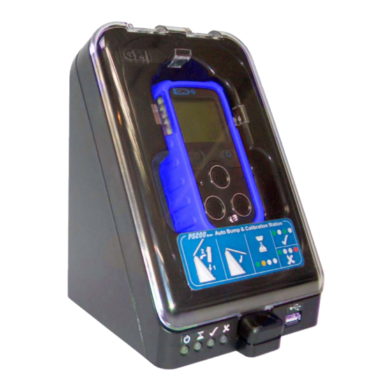
3M™ GMI™ PS200-LMP AUTO BUMP/CALIBRATION STATION INTRODUCTION 2. INTRODUCTION Clear Front Cover PS200-LMP Inserted into USB Port Cover Latch LED Status Indicators Figure 2-1: PS200-LMP Auto Bump Calibration Station 2.1. General Description The GMI Personal Surveyor 200-LMP Auto Bump/Calibration Station (ABC) provides the user with a quick, easy, and reliable method of gas testing PS200-LMP monitors. -
Page 12: Easy To Use
3M™ GMI™ PS200-LMP AUTO BUMP/CALIBRATION STATION INTRODUCTION The ABC will also charge a monitor after a bump test or calibration is complete. A mounting bracket is supplied allowing the ABC to be secured to a workbench. 2.2. Easy to Use Simply insert the PS200-LMP into the ABC and close the cover to initiate automatic testing. -
Page 13: Connections
3M™ GMI™ PS200-LMP AUTO BUMP/CALIBRATION STATION CONNECTIONS 3. CONNECTIONS 3.1. Calibration Gas Gas is supplied to the ABC from two gas cylinders via on-demand flow regulators, Tygon® tubing, and barbed adapters. Gas Cylinders Barbed Adapters Regulators Tygon® Tubing Figure 3-1: Calibration Gas Setup ) and carbon monoxide (CO). -
Page 14: Connect Gas Cylinder To Abc
3M™ GMI™ PS200-LMP AUTO BUMP/CALIBRATION STATION CONNECTIONS Gas Cylinder Concentrations ‘Use By’ Date Figure 3-2: Gas Cylinder Labels The concentrations listed on both gas cylinders must be consistent with the ABC configuration. Refer to for further information. Section 7. RE-CONFIGURING THE ABC 3.1.2. -
Page 15: Fitting
3M™ GMI™ PS200-LMP AUTO BUMP/CALIBRATION STATION CONNECTIONS CAUTION: When connecting the tubing to either the on-demand flow regulator or the barbed adapter, ensure the tubing fully connects to, and extends past, the last barb, as illustrated in Figure 3-4: Connecting Tubing to a Barbed Fitting Figure 3-4: Connecting Tubing to a Barbed Fitting 5. -
Page 16: In-Line Filter
3M™ GMI™ PS200-LMP AUTO BUMP/CALIBRATION STATION CONNECTIONS 3.2. In-line Filter During bump testing and calibration, ambient air is fed to the monitor from the ‘Air’ inlet. To improve ABC operation, GMI recommend fitting the supplied ‘Air’ in-line filter. 1. Push the barbed adapter (of the in-line filter assembly) into the ‘Air’ inlet, as illustrated in Figure 3-6: ‘Air’... -
Page 17: Power Supply
3M™ GMI™ PS200-LMP AUTO BUMP/CALIBRATION STATION CONNECTIONS 3.4. Power Supply Power is supplied to the ABC using the supplied Universal AC Power Adapter (12Vdc output). 1. Connect the 12VDC to the ABC, as illustrated in Figure 3-7: Connect Power Supply to ABC Figure 3-7: Connect Power Supply to ABC 2. - Page 18 3M™ GMI™ PS200-LMP AUTO BUMP/CALIBRATION STATION CONNECTIONS This page is intentionally left blank. 64220, Rev. 1/April 2019...
-
Page 19: Warm-Up Sequence
3M™ GMI™ PS200-LMP AUTO BUMP/CALIBRATION STATION WARM-UP SEQUENCE 4. WARM-UP SEQUENCE After power is applied, the ABC will perform a warm-up sequence lasting approximately 30 sec- onds. During this time, the four LEDs will illuminate in the following sequence: Figure 4-1: Warm-up Sequence (0-1 seconds) - Page 20 3M™ GMI™ PS200-LMP AUTO BUMP/CALIBRATION STATION WARM-UP SEQUENCE This page is intentionally left blank. 64220, Rev. 1/April 2019...
-
Page 21: Performing A Calibration/Bump Test
3M™ GMI™ PS200-LMP AUTO BUMP/CALIBRATION STATION PERFORMING A CALIBRATION/BUMP TEST 5. PERFORMING A CALIBRATION/BUMP TEST 5.1. Calibration 1. Verify two gas cylinders are connected to the ABC. 2. Verify that the ABC has completed its warm-up sequence and only one green LED is illuminated,... - Page 22 3M™ GMI™ PS200-LMP AUTO BUMP/CALIBRATION STATION PERFORMING A CALIBRATION/BUMP TEST Supply Nozzle Figure 5-3: Locate Monitor on Gas Supply Nozzle 6. Push the monitor back until correctly seated in the ABC, as illustrated in Figure 5-4: Monitor Cor- rectly Seated Figure 5-4: Monitor Correctly Seated 7.
-
Page 23: Close Front Cover
3M™ GMI™ PS200-LMP AUTO BUMP/CALIBRATION STATION PERFORMING A CALIBRATION/BUMP TEST Figure 5-5: Close Front Cover 8. Calibration will start automatically. The orange LED illuminates, indicating that calibration is in process, as illustrated in . Refer to Figure 5-6: Calibration in Progress Section APPENDIX A. -
Page 24: Pass Indication
3M™ GMI™ PS200-LMP AUTO BUMP/CALIBRATION STATION PERFORMING A CALIBRATION/BUMP TEST 12. After each range has been calibrated, the ABC's pump continues to operate for approximately 60 seconds. This draws air via the 'AIR' inlet to purge the ABC and monitor of gas. The gas values on the monitor's display will reduce to zero. -
Page 25: Abc Fault Indication
3M™ GMI™ PS200-LMP AUTO BUMP/CALIBRATION STATION PERFORMING A CALIBRATION/BUMP TEST Supply Nozzle Figure 5-10: Lift Monitor Clear of Gas Nozzle 20.Close the front cover of the ABC. NOTE: All calibration results are stored in the ABC. To access, refer to Section 6. - Page 26 3M™ GMI™ PS200-LMP AUTO BUMP/CALIBRATION STATION PERFORMING A CALIBRATION/BUMP TEST This page is intentionally left blank. 64220, Rev. 1/April 2019...
-
Page 27: Create/View Certificates
3M™ GMI™ PS200-LMP AUTO BUMP/CALIBRATION STATION CREATE/VIEW CERTIFICATES 6. CREATE/VIEW CERTIFICATES 6.1. Introduction Test results are stored in the ABC. These results can be transferred to the USB memory stick for viewing or printing on a PC/Laptop. The USB memory stick supplied with the ABC must be used. -
Page 28: Create A Certificate
3M™ GMI™ PS200-LMP AUTO BUMP/CALIBRATION STATION CREATE/VIEW CERTIFICATES 6.3. Create a Certificate Before results can be viewed for the first time, a certificate must be created. 1. Select PS200-LMP Settings.exe. The PS200-LMP Settings window is displayed, as illustrated Figure 6-3: PS200-LMP Settings Figure 6-3: PS200-LMP Settings 2. -
Page 29: Certificate Details
3M™ GMI™ PS200-LMP AUTO BUMP/CALIBRATION STATION CREATE/VIEW CERTIFICATES 3. The 'Certificate Printer' window is displayed. Data can be entered, as illustrated in Figure 6-5: Cer- . The data entered will appear on the generated certificate. tificate Details Figure 6-5: Certificate Details 4. -
Page 30: Calibration Certificate
3M™ GMI™ PS200-LMP AUTO BUMP/CALIBRATION STATION CREATE/VIEW CERTIFICATES The file name indicates: ♦ instrument serial number ♦ date of test ♦ time of test For example, the first file in indicates: Figure 6-6: Results on USB Memory Stick ♦ instrument serial number: 356650 ♦... -
Page 31: Bump Test Certificate
3M™ GMI™ PS200-LMP AUTO BUMP/CALIBRATION STATION CREATE/VIEW CERTIFICATES 9. The certificate is automatically stored on the USB memory stick as an html file. 10. If the ABC was configured to perform bump tests, the completed certificate will be as illustrated... -
Page 32: Access Previously Created Certificates
3M™ GMI™ PS200-LMP AUTO BUMP/CALIBRATION STATION CREATE/VIEW CERTIFICATES 6.4. Access Previously Created Certificates All previously generated certificates are stored in the Generated Certificates folder, as highlighted in Figure 6-9: Generated Certificates Folder Figure 6-9: Generated Certificates Folder This folder contains html files of all previously generated certificates as illustrated in... -
Page 33: Re-Configuring The Abc
3M™ GMI™ PS200-LMP AUTO BUMP/CALIBRATION STATION RE-CONFIGURING THE ABC 7. RE-CONFIGURING THE ABC 7.1. View/Edit Software Configuration The default configuration for the ABC is as follows: Bump Test or Calibration: Calibration Gas 1: 2.5% methane (CH4) and 100ppm carbon monoxide (CO) - Page 34 3M™ GMI™ PS200-LMP AUTO BUMP/CALIBRATION STATION RE-CONFIGURING THE ABC 4. Select Bump Test or Calibration as applicable (see Figure 7-3: Select Bump Test or Calibrate Figure 7-3: Select Bump Test or Calibrate 5. Enter the Gas 1 and Gas 2 concentrations as detailed on the gas cylinder labels. The example in illustrates Gas 1 concentrations of 2.4% Methane and 95 ppm...
- Page 35 3M™ GMI™ PS200-LMP AUTO BUMP/CALIBRATION STATION RE-CONFIGURING THE ABC Figure 7-5: Generate Settings Files 7. Verify that the ABC has completed its warm-up sequence and only one green LED is illuminated, as shown in Figure 7-6: ABC ON Indicator Figure 7-6: ABC ON Indicator 8.
- Page 36 3M™ GMI™ PS200-LMP AUTO BUMP/CALIBRATION STATION RE-CONFIGURING THE ABC This page is intentionally left blank. 64220, Rev. 1/April 2019...
-
Page 37: Specifications
3M™ GMI™ PS200-LMP AUTO BUMP/CALIBRATION STATION SPECIFICATIONS APPENDIX A. SPECIFICATIONS Table A-1: Windows Compatibility Windows 7, Windows 10 PS200-LMP settings are tested to run on the following Windows operating system: Table A-2: Gas Cylinder Permissible Concentrations Gas 1, % Methane (CH 1.0% to 4.0%... - Page 38 3M™ GMI™ PS200-LMP AUTO BUMP/CALIBRATION STATION SPECIFICATIONS This page is intentionally left blank. 64220, Rev. 1/April 2019...
-
Page 39: Usb Memory Stick Contents
3M™ GMI™ PS200-LMP AUTO BUMP/CALIBRATION STATION USB MEMORY STICK CONTENTS APPENDIX B. USB MEMORY STICK CONTENTS B.1. Accessing the Memory Stick Contents 1. The typical contents of the USB memory stick are illustrated in Figure B-1: USB Memory Stick Con-... - Page 40 3M™ GMI™ PS200-LMP AUTO BUMP/CALIBRATION STATION USB MEMORY STICK CONTENTS This page is intentionally left blank. 64220, Rev. 1/April 2019...
-
Page 41: Fit Mounting Bracket
3M™ GMI™ PS200-LMP AUTO BUMP/CALIBRATION STATION FIT MOUNTING BRACKET APPENDIX C. FIT MOUNTING BRACKET C.1. General Description The ABC is supplied with a mounting bracket and screws to secure it to a workbench (see Figure C-1: ). The bracket also provides the means to interconnect a series of ABC with Mounting Bracket Fitted ABCs. - Page 42 3M™ GMI™ PS200-LMP AUTO BUMP/CALIBRATION STATION FIT MOUNTING BRACKET Figure C-2: Attaching the Mounting Bracket to the ABC 4. Loosely attach the bracket to the base of the ABC using two pozi countersunk screws (supplied), as shown in Figure C-2: Attaching the Mounting Bracket to the ABC 5.
-
Page 43: Connect Multiple Abcs Together
3M™ GMI™ PS200-LMP AUTO BUMP/CALIBRATION STATION FIT MOUNTING BRACKET C.3. Connect Multiple ABCs Together Multiple ABCs can be connected by securing the brackets together. 1. Insert a double sems pozi pan screw through the bracket at the rear of one ABC. - Page 44 3M™ GMI™ PS200-LMP AUTO BUMP/CALIBRATION STATION FIT MOUNTING BRACKET This page is intentionally left blank. 64220, Rev. 1/April 2019...
-
Page 45: Technical Support
TECHNICAL SUPPORT APPENDIX D. TECHNICAL SUPPORT Congratulations on your purchase of a 3M™ GMI™ product. It is designed to provide you with reli- able trouble-free operation. If you have technical questions, need support, or if you need to return a product: •... - Page 46 3M™ GMI™ PS200-LMP AUTO BUMP/CALIBRATION STATION TECHNICAL SUPPORT 3M| Gas & Flame Detection Monroe Corporate Center P.O. Box 569 Monroe, NC 28111 Phone: (800) 247-7257 Fax: (704) 291-8330 Web-Site: https://gasdetection.3m.com 64220, Rev. 1/April 2019...
Need help?
Do you have a question about the PS200 Series and is the answer not in the manual?
Questions and answers