
Subscribe to Our Youtube Channel
Related Manuals for Vents VUT2 250 P EC


Summary of Contents for Vents VUT2 250 P EC
- Page 1 USER’S OPERATION MANUAL AIR HANDLING UNIT WITH SENSIBLE AND LATENT HEAT RECOVERY VUT2 250 P EC VUE2 250 P EC VUTE2 250 P EC...
-
Page 2: Table Of Contents
VU..2 250 P EC VU..2 250 P EC CONTENTS Introduction ....................Use ........................Delivery set ....................Structural designation key ..............Technical data ..................... Safety requirements ................. Structure and operating logic .............. Mounting and set-up ................Condensate drainage ................Connection to power mains ..............Unit control .................... -
Page 3: Introduction
INTRODUCTION The present user’s operation manual contains technical description, data sheet, installation and mounting guidelines for the air handling unit with heat (energy, heat and energy) recovery VU_ 2 250 P EC (hereinafter referred as the unit). The unit with sensible and latent heat recovery is designed to save heating and cooling costs by means of thermal energy utilization and is one of the energy saving components used in buildings and premises. -
Page 4: Structural Designation Key
VU..2 250 P EC VU..2 250 P EC STRUTURAL DESIGNATION KEY 2 250 Motor type electronically commutated Design Features P – suspension-type Capacity, m³/h Number of heat exchangers, units Unit Type VUT – unit with sensible heat recovery heat exchangers VUE –... -
Page 5: Safety Requirements
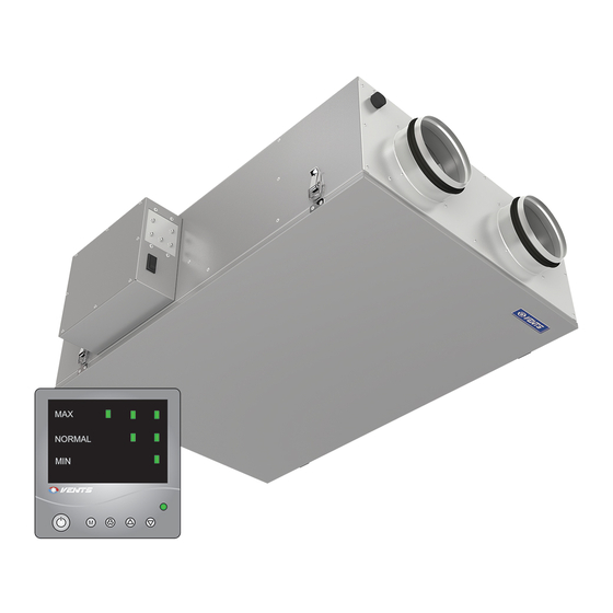
The unit is designed for operation in an enclosed area at ambient temperatures from +1ºC to + 60 ºC at relative humidity of up to 80%. Hazardous parts access and water ingress protection standard: Unit motors - IP 44; Unit assembly connected to air ducts - IP 22. The unit series designations, their main outside and connecting dimensions, appearance and technical parameters are given on Figure 1 and in Table 1. -
Page 6: Structure And Operating Logic
Cross-fl ow plate heat exchanger - for VUT2 250 P EC unit - sensible heat exchanger - 2 pcs. - for VUTE2 250 P EC unit - sensible heat exchanger - 1 pcs. and latent heat exchanger - 1 pcs. -
Page 7: Mounting And Setup
MOUNTING AND SETUP While installing the unit ensure convenient access for subsequent maintenance or repair. The units are mounted to the ceiling using belts rigidly attached to a horizontal surface (Fig. 3) or threaded rods which are securely installed in threaded expansion bolts driven into the ceiling. Prior to installation make sure that the casing is free from any foreign objects such as wrapping fi lm or paper. -
Page 8: Connection To Power Mains
VU..2 250 P EC VU..2 250 P EC Fig. 4. Condensate drainage The condensate drainage system is designed for normal operation in premises with air temperatures above 0 °C. If the expected air temperatures are below 0 °C the condensate drainage system must be equipped with heat insulation and pre-heating facilities. -
Page 9: Unit Control
UNIT CONTROL The unit is controlled from the control panel (Fig. 5). Indication of main ventilation modes (in the Setup mode the min flow speed is displayed) Indicator Operation/Setup Flow Rate Up button in the Setup mode (disabled in the Operation mode) Flow Rate Down button in the Setup mode (disabled in the Operation mode) Ventilation mode selection button... - Page 10 VU..2 250 P EC VU..2 250 P EC Table 2. Ventilation mode display on the control panel Mode Indicator combination Operation mode Minimum fl ow rate Unlimited time Minimum fl ow rate + 80 m³/h NORMAL Time: 30 minutes. Maximum fl ow rate Unlimited time Setup Mode.
- Page 11 Table 3. Indication Flow Rate, m³/h...
- Page 12 VU..2 250 P EC VU..2 250 P EC Control panel connection. The connection port side view of the control panel is given on Fig.6. 1 2 3 4 1 - Control voltage U_EC1; 2 - Control voltage U_EC2; 3 - Supply voltage +12V; 4 - Negative power lead.
-
Page 13: Maintenance
MAINTENANCE The unit must undergo technical maintenance 3 or 4 times a year. The technical maintenance includes general cleaning of the unit and the following operations: Filter service (3-4 times a year). Contaminated fi lters increase air resistance thus impairing supply air delivery into the premises. The fi lters should be cleaned as they get dirty, but at least 3-4 times a year. - Page 14 VU..2 250 P EC VU..2 250 P EC Fig. 8. Filter and heat exchanger maintenance Fig. 9. Control unit maintenance...
-
Page 15: Fault Handling
FAULT HANDLING Possible Malfunctions and Fault Handling Problem Possible reasons Fault handling Make sure that the unit is properly Fan (Fans) The unit is not connected to the connected to the power mains and make will not start power mains. any corrections, if necessary. -
Page 16: Storage And Transportation Rules
VU..2 250 P EC VU..2 250 P EC STORAGE AND TRANSPORTATION RULES Store the unit in the manufacturer’s original packing box in a closed ventilated premise with temperature range from +10°C to +40°C and relative humidity less than 80% (at +20°C). Vapours or particles which can cause corrosion or damage the insulation or connection tightness are not allowed in the storage environment. -
Page 17: Acceptance Certificate
ACCEPTANCE CERTIFICATE The air handling unit with heat recovery VU ___ 2 250 P EC has been duly certifi ed as serviceable. We hereby declare that the product complies with the essential protection requirements of Electromagnetic Council Directive 2004/108/EC, 89/336/EEC and Low Voltage Directive 2006/95/EC, 73/23/EEC and CE-marking Directive 93/68/EEC on the approximation of the laws of the Member States relating to electromagnetic compatibility. - Page 18 VU..2 250 P EC VU..2 250 P EC...
- Page 20 V83EN-03...
Need help?
Do you have a question about the VUT2 250 P EC and is the answer not in the manual?
Questions and answers