Table of Contents
Advertisement
Quick Links
USER'S MANUAL
VUT R 400 WH EC A17
VUT R 700 WH EC A17
VUT R 900 WH EC A17
VUT R 1200 WH EC A17
VUT R 1500 WH EC A17
VUT R 2000 WH EC A17
VUT R 400 WH EC A18
VUT R 700 WH EC A18
VUT R 900 WH EC A18
VUT R 1200 WH EC A18
VUT R 1500 WH EC A18
VUT R 2000 WH EC A18
Heat recovery air handling unit
equipped with a water heater
Advertisement
Table of Contents

Subscribe to Our Youtube Channel
Related Manuals for Vents VUT R 400 WH EC A17


Summary of Contents for Vents VUT R 400 WH EC A17
- Page 1 USER’S MANUAL VUT R 400 WH EC A17 VUT R 700 WH EC A17 VUT R 900 WH EC A17 VUT R 1200 WH EC A17 VUT R 1500 WH EC A17 VUT R 2000 WH EC A17 VUT R 400 WH EC A18...
-
Page 2: Table Of Contents
www.ventilation-system.com CONTENTS Safety requirements Purpose Delivery set Designation key Technical data Unit design and operating logic Mounting and set-up Connection to power mains Unit control Technical maintenance Storage and transportation regulations Manufacturer's warranty Acceptance certificate Seller information Installation certificate Warranty card RECYCLE AT THE END OF THE SERVICE LIFE. -
Page 3: Safety Requirements
This user’s manual consisting of the technical details, operating instructions and technical specification covers the installation and mounting of the VUT R WH EC heat recovery air handling unit (hereinafter referred to as «the unit»). SAFETY REQUIREMENTS • Read the user’s manual carefully prior to installing and operating the unit. •... - Page 4 www.ventilation-system.com UNIT MOUNTING AND OPERATION SAFETY PRECAUTIONS • Disconnect the unit from power mains prior to • Do not allow children to operate the unit. any technical maintenance. • When the unit generates unusual sounds, • Do not store any explosive or highly flammable odour or emits smoke disconnect it from substances in close proximity to the unit.
-
Page 5: Purpose
PURPOSE The unit is designed to ensure continuous mechanical air exchange in houses, offices, hotels, cafés, conference halls, and other utility and public spaces as well as to recover the heat energy contained in the air extracted from the premises to warm up the filtered stream of supply air. The unit is not intended for organizing ventilation in swimming pools, saunas, greenhouses, summer gardens, and other spaces with high humidity. -
Page 6: Technical Data
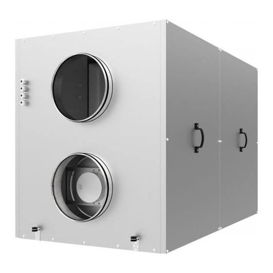
www.ventilation-system.com TECHNICAL DATA The unit is designed for indoor application with the ambient temperature ranging from +1 °C up to +40 °C and relative humidity up to 80 %. In order to prevent condensation on the internal walls of the units, it is necessary that the surface temperature of the casing is 2-3 °C higher than the dew point temperature of the transported air. - Page 7 Overall dimensions of VUT R 400/700/900 WH EC ØD Overall dimensions of VUT R 1200/1500 WH EC 1200 1500 Overall dimensions of VUT R 2000 WH EC 2000 Dimensions [mm] Unit model øD VUT R 400 WH EC 1050 1167 VUT R 700 WH EC 1210 1326...
- Page 8 www.ventilation-system.com Calculation of water heater parameters for VUT R 400/700/900 WH EC Air temperature downstream of the heater [°C] Heating coil capacity [kW] Air speed inside the heater [m/s] Air ow through the heating coil [m Water ow through the water heating coils [l/s] Water heater parameters calculation example: ƒ...
- Page 9 Calculation of water heater parameters for VUT R 1500/2000 WH EC Air temperature downstream of the heater [°C] Heating coil capacity [kW] Air speed inside the heater [m/s] Air ow through the heating coil [m Water heater parameters calculation example: Water ow through the water heating coils [l/s] ƒ...
-
Page 10: Unit Design And Operating Logic
www.ventilation-system.com UNIT DESIGN AND OPERATING LOGIC The unit has the following operating logic: Warm stale extract air from the room flows to the unit, where it is filtered by the extract filter. Then the air is moved through the rotary heat exchanger and is exhausted outside with the exhaust fan. -
Page 11: Mounting And Set-Up
MOUNTING AND SET-UP While mounting the unit provide enough access for maintenance or repair work. The minimum recommended clearances between the unit and the adjoining walls are given in the figure below. Before starting the unit make sure that the rotary heat exchanger cells are clean and free from damage. Check the belt tension. The tension force is regulated by the spring on the motor suspension mount. - Page 12 www.ventilation-system.com WATER HEATER CONNECTION Use a pipe spanner for connection of a water heater. Do not apply excessive force while tightening the water works fittings when connecting a water heater. A pipeline system connected to a water heater is designed for normal operation in premises with air temperatures above 0 °C! If the temperature is expected to drop below 0°C it is necessary to provide appropriate thermal insulation or air heating at the site of unit operation.
- Page 13 TH-TUNE CONTROL PANEL INSTALLATION To install the rear part of the control panel use a suitable mounting box (minimum diameter 65 mm and minimum depth 31 mm). 1. Use a screwdriver to pull the front and the rear sides of the control 2.
- Page 14 www.ventilation-system.com PGD1 CONTROL PANEL INSTALLATION Connect the pGD1 control panel to the controller connector (see figure on page 13) using the 6P6C (PLUG-6P6C-P-C2) phone plug. The maximum length of the phone cable is 50 m. To mount the control panel on a wall route the phone cable to the selected location. 1.
-
Page 15: Connection To Power Mains
CONNECTION TO POWER MAINS DISCONNECT THE UNIT FROM POWER SUPPLY PRIOR TO ANY OPERATIONS WITH THE UNIT. CONNECTION OF THE UNIT TO POWER MAINS IS ALLOWED BY A QUALIFIED ELECTRICIAN WITH A WORK PERMIT FOR THE ELECTRIC UNITS UP TO 1000 V AFTER CAREFUL READING OF THE PRESENT USER’S MANUAL. -
Page 16: Unit Control
www.ventilation-system.com UNIT CONTROL The unit is equipped with a built-in automatic control system and a control panel. The automatic control system has the following functions: Control unit of VUT R 400-2000 WH EC 1. Turning the unit on/off 2. Unit operation mode selection: Automatic mode, Ventilation mode (can be enabled only from the pGD1 control panel). - Page 17 UNIT CONTROL PANELS The unit is controlled via the th-Tune or pGD1 control panel. Button Functions Operation mode selection: set the operation mode according to the procedure described on page 20. Fan speed selection: set the desired speed level (Low, High or Me- dium).
- Page 18 www.ventilation-system.com Connect the pGD1 control panel to the controller con- nector (see figure on page 13) using the 6P6C (PLUG-6P6C- P-C2) phone plug. The maximum length of the phone cable is 50 m. The pGD1 offers extended functionality and has identi- cal settings entered via the controller screen (see “Controller functions and menu”).
- Page 19 CONTROLLER FUNCTIONS AND MENU The controller has the following controls and indicators: Backlit LCD display. The display screen shows the current parameters of the system operation, temperature values, pre-set parameters and alarms. Control buttons of the automatic control system: Enter Enters speci c modes: editing a parameter, saving an edited parameter and function list navigation Down...
- Page 20 www.ventilation-system.com To modify the unit operation parameters move the cursor to the required line using the button. Then use the buttons to set the desired value and then press the to confirm. To exit the parameter change mode without saving the changes press the button.
- Page 21 TEMPERATURE SETTING To modify the temperature setting set the cursor at “Setpoint” by using the button. Then use the buttons to set the desired temperature value and then press the to confirm. Temperature setting range: from +15 °C up to +30 °C. FAN SPEED SETTING To select the desired fan speed set the cursor at “Fan speed”...
- Page 22 www.ventilation-system.com Page 2/3 contains the following parameters: Page 3/3 contains the controller firmware information. • Outside air temperature [°C] • Supply air temperature [°C] • Exhaust duct temperature [°C] • Exhaust duct temperature [°C]. When selecting “Main sensor: Exh. Air” in the “Parameter” field. •...
- Page 23 5. Setting up other entries. 6. Copying schedule entries to other days. Other entries are set up similarly. After programming all the necessary entries they can be copied to any other day of the week as follows: 1. Use the button to set the cursor at “Copy to”.
- Page 24 www.ventilation-system.com 4. Selecting the special day setpoint. 5. Setting up other special days. Other special days are set up similarly. Press the button to select the “Set. ” parameter and then use the buttons to select the setpoint required on the special day. Once done with the special day setup press the button to save the changes.
- Page 25 Page 2/04. Setting up temperature setpoints. T1 is the setpoint for the supply air temperature at which the unit will switch to a lower speed in case of failure to attain the pre-pro- Press the button to select the temperature setpoint and then use grammed temperature conditions.
-
Page 26: Technical Maintenance
www.ventilation-system.com TECHNICAL MAINTENANCE DISCONNECT THE UNIT FROM POWER MAINS PRIOR TO ANY MAINTENANCE OPERATIONS. Maintenance operations of the unit are required 3-4 times per year. Maintenance includes general cleaning of the unit and the following operations: 1. Filter maintenance: Dirty filters increase air resistance in the system and reduce supply air volume. The filters require cleaning not less than 3-4 times per year. On elapsing of 3,000 operating hours the unit controller generates the filter replacement or cleaning alert. -
Page 27: Storage And Transportation Regulations
3. Fan maintenance (once per year). Even in case of regular maintenance of the filters, some dust may accumulate inside the fans and reduce the fan performance and supply air flow. Clean the fans with a soft cloth or brush. Do not use water, aggressive solvents or sharp objects as they may damage the impeller. 4. -
Page 28: Manufacturer's Warranty
www.ventilation-system.com MANUFACTURER’S WARRANTY The manufacturer hereby warrants normal operation of the unit for 24 months after the retail sale date provided the user’s observance of the transportation, storage, mounting and operation regulations. Should any malfunctions occur in the course of the unit operation through the Manufacturer’s fault during the guaranteed period of operation the user is entitled to elimination of faults by the manufacturer by means of warranty repair at the factory free of charge. -
Page 29: Acceptance Certificate
ACCEPTANCE CERTIFICATE Unit Type Heat recovery air handling unit Model VUT R __________ WH EC A __________ Serial Number Manufacture Date We hereby declare that the product complies with the essential protection requirements of Electromagnetic Council Directive2004/108/EC, 89/336/EEC and Low Voltage Directive 2006/95/EC, 73/23/EEC and CE-marking Directive 93/68/EEC on the approximation of the laws of the Member States relating to electromagnetic compatibility. - Page 30 www.ventilation-system.com...
- Page 32 V78EN-05...
Need help?
Do you have a question about the VUT R 400 WH EC A17 and is the answer not in the manual?
Questions and answers