
Related Manuals for Terayon eMTA TA 102

Summary of Contents for Terayon eMTA TA 102
- Page 1 Terayon Communication Systems TA 102/202 eMTA Technical Support Guide Part No. 8500276 Rev B December 2004...
- Page 2 Contacting Terayon Communication Systems You can contact Terayon Communication Systems as follows: Telephone: (888) 783-7296 (888-7-Terayon) or 408-235-5823, 24 hours a day, 7 days a week • Postal mail: • Terayon Communication Systems 4988 Great America Parkway Santa Clara, CA 95054, U.S.A.
-
Page 3: Table Of Contents
Package Contents ..........2-2 Terayon TA-102 or TA-202 MTA Modem Package Contents ..2-2 System Requirements . - Page 4 TA-102/202 eMTA Start Up ........2-14 Front Panel Indicators .
- Page 5 OSS Support Systems (OSS) ........4-7 Provisioning Servers .
-
Page 7: Why Use This Guide
Why Use This Guide? If your goal is to learn about the Terayon TA 102/202 eMTA, you are in the right place. This guide provides a brief overview of the TA 102/202 eMTA as well as information about how to install it and get it up and running. -
Page 8: Icons Used In This Guide
Chapter 2, “Installation” This chapter tells you how to install the TA 102/202 eMTA. You’ll find out what tools you’ll need, what the environmental and power requirements are, and a slew of installation instructions. Chapter 3, “Troubleshooting” This chapter contains trouble shooting information intended to help you identify and correct TA 102/202 eMTA malfunctions. -
Page 9: Chapter 1 Overview
Chapter 1 Overview The Terayon TA 102 and 202 are PacketCable compliant embedded Multimedia Terminal Adapters (eMTAs) that perform all the control functions required for PacketCable telephony calls. Chapter 1 provides a brief overview of TA 102/202 eMTA features and functions. The material presented includes: •... -
Page 10: What Is An Embedded Mta
Chapter 1 Overview What is an Embedded MTA? What is an Embedded MTA? No matter how much of a cyberpro you are — or how much of a novice, there’s always something new to learn. The astute reader (you of course) may be wondering what an embedded MTA is. -
Page 11: The Ta 102/202 Emta At A Glance
Chapter 1 Overview The TA 102/202 eMTA at a Glance Built around the Terayon TJ 715x cable modem, the TA 102 (DOCSIS) and the TA 202 (Euro-DOCSIS) lets cable operators offer simultaneously to their subscribers, both high speed data and voice services. The TA 102 and TA 202 are two-line, PacketCable compliant eMTAs designed for indoor use. -
Page 12: Hardware Architecture
Chapter 1 Overview Hardware Architecture Hardware Architecture In this section we delve into what’s inside the TA 102/202 eMTA. Figure 1-3 shows the basic architecture of the eMTA, and the following sections describe its I/O interfaces. 16 MB SDRAM CABLE MODEM CONTROL RF IN/OUT... -
Page 13: Ta 102/202 Emta Interfaces
Hardware Architecture Chapter 1 Overview TA 102/202 eMTA Interfaces An eMTA must interact and communicate with its environment so it can perform useful tasks. It communicates with its environment through interfaces — electrical links that connect two or more pieces of equipment together. The TA 102/202 eMTA provides four interfaces for communicating with its environment. -
Page 14: High Speed Data Interfaces
Chapter 1 Overview Hardware Architecture High Speed Data Interfaces The TA 102/202 eMTA is versatile in that it offers two methods for connecting a subscriber PC to a CATV cable. There is a USB connection and an Ethernet connection. Only one connection (Ethernet or USB) is permitted. Ethernet Interface For an Ethernet connection, the point of connection between a subscriber PC and the TA 102/202 eMTA is the Ethernet Interface. -
Page 15: Speech Codec
Hardware Architecture Chapter 1 Overview Additionally, both line interfaces support all telephony services, such as Caller ID, Call forwarding, Call Waiting, etc. For a European application, the POTS interface can func- tion with equipment compliant to the European Telecommunications Standards Insti- tute (ETSI) specification. -
Page 16: Mib Support
Chapter 1 Overview MIB Support The program that runs the DSP is called an audio codec. A codec (coined from coder/ decoder) is a pair of algorithms. One algorithm takes analog input and delivers digital output. The other algorithm does the opposite. NOTE NOTE: The PacketCable 1.0 Specification only supports audio codecs. -
Page 17: Security
Security Chapter 1 Overview The TA 102/202 eMTA provides all of the following IETF IPCDN MIB features: • Cable Device MIB as per [RS99a] (or the RFC version when published). • Support for 32 concurrent filters in the Cable Device MIB without performance deg- radation. -
Page 18: Packetcable
Chapter 1 Overview Standards Compliancy PacketCable The TA 102/202 eMTA is fully compliant with the requirements described in the following PacketCable documents: • PKT-SP-CODEC-I05-040113 • PKT-SP-DQOS-I09-040402 • PKT-SP-EC-MGCP-I09-040113 • PKT-SP-MIB-MTA-I07-030728 • PKT-SP-MIB-SIG-I07-030728 • PKT-SP-MIBS-I07-030728 • PKT-SP-PROV-I09-040402 • PKT-SP-SEC-I10-040113. Euro-PacketCable The TA 102/202 eMTA is fully compliant with the requirements described in the TS 101 909 series documents (part 1 to part 26) 1-10 TA 102/202 Technical Support Guide... -
Page 19: Chapter 2 Installation
Chapter 2 Installation You may never have to install the TA-102/202 eMTA, but you may have to field telephone calls from customers that are having problems installing their TA-102/ 202 eMTA. To assist you with answering customer installation questions, Chapter 2 provides a TA-102/202 eMTA installation guide similar to the installa- tion guide the customer receives with the equipment. -
Page 20: Getting Started
Getting Started This installation guide is designed for anyone who wants all the “how-to” information about installing the Terayon TA-102 or TA-202 embedded Multimedia Terminal Adapter (eMTA). You have probably heard of online help. Well, think of this installation guide as onside help. - Page 21 Getting Started Chapter 2 Installation TERAYON MULTIMEDIA TERMINAL ADAPTER MODEM MODEL TA-102 or TA-202 POWER ADAPTER NOTE: The appropriate Power Adapter is included with your modem. b l e L i n L i n - 1 0 MODEM STAND...
-
Page 22: Mta Installation
CABLE OUTLET SIGNAL FROM CABLE CO. TV AND DATA CABLE PC TOWER CABLE SPLITTER ETHERNET OR USB CABLE COAX CABLE "A" (DATA) TERAYON w er C ab DOCSIS or EuroDOCSIS D at L in L in MTA MODEM -1 02... -
Page 23: Modem Connectors
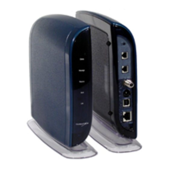
MTA Installation Chapter 2 Installation Modem Connectors Take a moment to familiarize yourself with the TA-102/202 eMTA connectors identified in Figure 2-3. An explanation of each connector follows the illustration. Figure 2-3 TA-102/202 eMTA Connectors 1 - RF Cable Connector Connects the TA-102/202 eMTA to the incoming signal from the cable company via a cable splitter. -
Page 24: Catv Coax Cable To Ta-102/202 Emta
Chapter 2 Installation MTA Installation CATV Coax Cable to TA-102/202 eMTA In order for the TA-102/202 eMTA and the subscriber’s PC to access the Internet, you need to connect the coaxial cable that comes from the cable outlet to the eMTA. This is typically done using a cable splitter. -
Page 25: Connecting The Power Adapter To The Ta-102/202 Emta
7. Remove the TA-102/202 eMTA from its box and place it near the computer. 8. Connect the remaining end of coax Cable “A” (Data) to the RF connector on the TA-102/202 eMTA as shown in Figure 2-5. Tighten the connection with a 7/16 wrench. TERAYON MULTIMEDIA TERMINAL ADAPTER MODEM MODEL TA-102 or TA-202... - Page 26 2. Using Figure 2-6 as a guide, align the key groove on the DC Output plug with the key slot in the DC Power Input jack on the back of the eMTA. 3. Push the plug into the jack so the cable is firmly connected. TERAYON MULTIMEDIA TERMINAL ADAPTER MODEM MODEL TA-102 or TA-202...
-
Page 27: Connecting The Ta-102/202 Emta To A Pc
MTA Installation Chapter 2 Installation Connecting the TA-102/202 eMTA to a PC If the customer computer is to communicate with the TA-102/202 eMTA and the Internet, it must be equipped with a network interface. Today’s computers are typically equipped with either a 10/100 Base-T Ethernet port or a Universal Serial Bus (USB) port. - Page 28 Chapter 2 Installation MTA Installation PC TOWER REAR VIEW TERAYON MULTIMEDIA TERMINAL ADAPTER MODEM MODEL TA-102 or TA-202 RF CABLE SPLITTER RJ-45 ETHERNET PORT 10/100 BASE-T ETHERNET CABLE ETHERNET INTERFACE CARD ETHERNET PORT Figure 2-7 Connecting the 10/100Base-T Ethernet Cable...
-
Page 29: Connecting The Usb Cable
MTA Installation Chapter 2 Installation Connecting the USB Cable In order for the computer USB Interface to pass data back and forth to the TA-102/202 eMTA, you must connect a USB cable to the TA-102/202 eMTA USB port and the USB port on the back of the computer. - Page 30 Chapter 2 Installation MTA Installation TERAYON PC TOWER MULTIMEDIA TERMINAL ADAPTER REAR VIEW MODEL TA-102 or TA-202 RF CABLE SPLITTER "A" CONNECTOR "B" CONNECTOR PC USB PORT USB PORT USB CABLE Figure 2-8 Connecting the USB Cable 2-12 TA 102/202 Technical Support Guide...
-
Page 31: Connecting A Telephone To The Ta-102/202 Emta
11 jack on the back of the unit. 4. If you have a second telephone, insert the telephone cable RJ-11 plug into the Line 2 RJ-11 jack on the back of the unit as shown in Figure 2-9. TERAYON MULTIMEDIA TERMINAL ADAPTER MODEM MODEL TA-102 or TA-202... -
Page 32: Ta-102/202 Emta Start Up
Chapter 2 Installation MTA Installation TA-102/202 eMTA Start Up To start operating the TA-102/202 eMTA, do the following: 1. Plug the Power Adaptor into an appropriate AC power outlet. Once the TA-102/202 eMTA is properly connected and power is applied, it will auto- matically boot-up and start scanning for an active downstream channel. -
Page 33: Front Panel Indicators
MTA Installation Chapter 2 Installation Front Panel Indicators The indicator LEDs on the front panel of the TA-102/202 eMTA tell you what’s happen- ing during a communications session. The table below tells you what each LED indica- tor means Note that the customer has this table in their installation guide. Color Definition Power... -
Page 34: Bu 802 Battery Backup Unit Installation
To keep a TA-102/202 eMTA operational during a local AC power failure, Terayon pro- vides the BU 802 Battery Backup Unit. As a battery backup unit the BU 802 senses an AC power loss and automatically switches to battery power so the TA-102/202 eMTA remains operational during an AC power outage. - Page 35 BU 802 Battery Backup Unit Installation Chapter 2 Installation Two 2S1P Lithium-Ion Two 2S2P Lithium-Ion One 2S2P Lithium-Ion Battery Pack Battery Packs Battery Packs & One 2S1P Lithium-Ion Battery Pack One 2S1P Lithium-Ion One 2S2P Lithium-Ion Battery Pack Battery Pack Figure 2-11 BU 802 Battery Pack Configurations WARNING: There is a danger of explosion if battery packs are replaced incorrectly.
-
Page 36: Readying The Installation Site
Chapter 2 Installation BU 802 Battery Backup Unit Installation Readying the Installation Site Before you begin to install the BU 802, take the time to do a few get-ready steps: 1. Perform a site survey to determine the best method for installing the BU 802 (desk- top or wall mounting). -
Page 37: Battery Installation
BU 802 Battery Backup Unit Installation Chapter 2 Installation Battery Installation Installing batteries into the BU 802 involves removing the unit back plate, connecting battery cables to battery cable connectors, and placing battery packs into the individual battery compartments. The only tool you will need is a medium size Phillips screw driver. - Page 38 Chapter 2 Installation BU 802 Battery Backup Unit Installation BU 802 BATTERY BACKUP UNIT BU 802 BATTERY BACKUP UNIT BATTERY 1 CABLE CONNECTOR BATTERY CABLE RECEPTACLE BATTERY 2 CABLE CONNECTOR BATTERY CABLE RECEPTACLE Figure 2-13 BU 802 Battery Pack Installation BU 802 BATTERY BACKUP UNIT DC POWER CABLE TO TA-102/202 eMTA...
-
Page 39: Emta/Bbu Mating
BU 802 Battery Backup Unit Installation Chapter 2 Installation eMTA/BBU Mating Once you have installed battery packs into the BU 802, its time to mate the TA-102/202 eMTA with the BU 802 Battery Backup Unit. To do this, follow these steps: 1. -
Page 40: Bu 802 Wall Mounting
Chapter 2 Installation BU 802 Battery Backup Unit Installation BU 802 Wall Mounting Mounting the BU 802 to a wall location involves marking and drilling mounting holes, installing mounting screws or Molly-Bolts, and mounting the unit onto the mounting screws. To perform these tasks you will need the following tools: •... - Page 41 BU 802 Battery Backup Unit Installation Chapter 2 Installation 4. Using a hand or power drill, drill 2 holes into the mounting surface at the locations you marked on the mounting surface. Make the depth of the holes equal to the approximate length of the screws you are going to use.
-
Page 42: Power Up And Check
3. Using Figure 2-18 as a guide, align the key groove of the Power Adapter DC Output connector with the key slot in the BU 802 voltage input jack, then push the connector into the jack so the cable is firmly connected TERAYON DOCSIS MODEM MODEL TA-102 or TA-202 POWER ADAPTER... -
Page 43: Battery Status Led
BU 802 Battery Backup Unit Installation Chapter 2 Installation Battery Status LED To keep subscribers informed of battery conditions, BU 802 Battery Backup Units are equipped with a Battery Status LED. Located at the bottom right side of the BU 802, as shown in Figure 2-19, this multi-colored LED indicates battery condition. - Page 44 Chapter 2 Installation BU 802 Battery Backup Unit Installation If your BU 802 Battery Backup Unit is using a Default Battery Status LED pattern, use Table 2-1 to determine battery pack status. Table 2-1 Battery LED Status Conditions, Default Pattern LED Color Battery Status Green...
-
Page 45: Bu 802 Specifications
BU 802 Battery Backup Unit Installation Chapter 2 Installation BU 802 Specifications Table 2-3 BU 802 Battery Backup Unit Specifications Specification Description Backup Time Standby Time (on-hook state): Rattings are for standard 4300 mA and • Up to 2 hours, one 2S1P battery pack. 2200 mA battery packs. -
Page 47: Chapter 3 Troubleshooting
Chapter 3 Troubleshooting Chapter 3 contains troubleshooting information intended to help you identify and correct TA 102/202 eMTA malfunctions. Troubleshooting information is con- tained in Table 3-1 and in the section entitled ‘Typical End User Problems and Solutions”. Before getting into troubleshooting concepts, it maybe useful to briefly review the normal power-up sequence of the TA 102/202 eMTA. - Page 48 Chapter 3 Troubleshooting 19. MTA downloads configuration file from TFTP server 20. MTA sends a final INFORM message to the provisioning server Line 1 and 2 LEDs Blinking Rapidly 21. MTA finds the KDC associated with the Call Management Server (CMS) 22.
-
Page 49: Troubleshooting Summary
Troubleshooting Summary Chapter 3 Troubleshooting Troubleshooting Summary Table 3-1 shows the major problems that occur and the corrective action that can be taken. Some of these actions can be taken by the end user, other actions must be performed by a network administrator at the headend. Table 3-1 Troubleshooting summary Problem... -
Page 50: Typical End User Problems And Solutions
Chapter 3 Troubleshooting Typical End User Problems and Solutions Typical End User Problems and Solutions The following is a summary of typical problems and solutions end users encounter when installing a TA 102/202 eMTA. Problem: I cannot access my E-mail or Internet Service. Possible Solution: Check all connections. -
Page 51: Problem
MTA modem, see Figure 3-1. 2. Push the pointed object to depress the Reset Switch. This action forces the MTA modem to re-boot. TERAYON MULTIMEDIA TERMINAL ADAPTER MODEM MODEL TA-102 or TA-202 DATA SWITCH... -
Page 52: Problem
Chapter 3 Troubleshooting Typical End User Problems and Solutions 4. If all the MTA modem LEDs are still all turned ON after resetting the modem, dis- connect the Power Adapter from the AC power outlet. Wait a few seconds, then recon- nect the Power Adapter to the AC power outlet. -
Page 53: Problem
ON position, and stop the PC LED blinking. Figure 3-2 Pressing the Data Switch NOTE: You can disable the Data Switch by implementing the Terayon TLV- NOTE 11 MIB in the MTA modem configuration file. TA 102/202 Technical Support Guide... -
Page 54: Problem
Note that Terayon tests all TA 102/202 eMTAs before shipping to verify the product is fully compliant with voice quality requirements. -
Page 55: Ta 102/202 Emta Front Panel Led Definitions
TA 102/202 eMTA Front Panel LED Definitions Chapter 3 Troubleshooting TA 102/202 eMTA Front Panel LED Definitions The indicator LEDs on the front panel of the TA 102/202 eMTA tell you what’s happen- ing during a communications session. The table below tells you what each LED indica- tor means. -
Page 57: Chapter 4 Packetcable Network Architecture
Chapter 4 PacketCable Network Architecture If music, video and other multimedia content can be shot across HFC networks, why not conduct telephone conversations? With the PacketCable project from CableLabs conducting a phone conversation via an HFC network is now a real- ity. - Page 58 Chapter 4 PacketCable Network Architecture PacketCable Network Architecture PacketCable Network Architecture What makes up a PacketCable Network you ask? At a very high level, a PacketCable network consists of three networks. Two of the networks are the familiar DOCSIS HFC Access Network and the Managed IP Network (headend).
-
Page 59: Packetcable Functional Components
PacketCable Functional Components Chapter 4 PacketCable Network Architecture The functional components of the HFC network include: a Cable Modem (CM), a Multi- media Terminal Adapter (MTA) or an eMTA (a cable modem with an embedded MTA) and a Cable Modem Termination System (CMTS). Referring again to Figure 4-1, the Managed IP Network provides the long-haul connec- tivity between other Managed IP and HFC Access Networks. -
Page 60: Cable Modem (Cm)
Chapter 4 PacketCable Network Architecture PacketCable Functional Components In the current release of PacketCable specifications, it is assumed the MTA is tightly coupled to a cable modem (CM). An MTA can be a standalone device or it can be embed- ded within the cable modem —... -
Page 61: Cmts Gate
PacketCable Functional Components Chapter 4 PacketCable Network Architecture The CMTS is also responsible for managing access network (cable modem network) resources for PacketCable services. Access network resources are first reserved when service is requested, then committed when service is delivered, and released when the service is complete. -
Page 62: Call Management Server (Cms)
Chapter 4 PacketCable Network Architecture PacketCable Functional Components Call Management Server (CMS) The CMS is a trusted network element that resides in the cable operator’s Managed IP Network. It is responsible for initiating, processing, and call forward signaling information. For example, when a subscriber places a call, the identity of the destination party (in the form of digits) is passed to the CMS. -
Page 63: Announcement Server (Ans)
PacketCable Functional Components Chapter 4 PacketCable Network Architecture Announcement Server (ANS) An Announcement Server is a network device that manages and plays informational tones in response to events that occur on the network. Announcement Server (ANS) Manages and plays informational tones and messages in response to events that occur on the network. -
Page 64: Provisioning Servers
Chapter 4 PacketCable Network Architecture PacketCable Functional Components Associated hardware components include: • Provisioning servers • KDC servers for security • RKS servers for record keeping. Provisioning Servers Two kinds of provisioning occur in PacketCable, one on the IP side and one on the PacketCable side. -
Page 65: Pstn Gateway
PacketCable Functional Components Chapter 4 PacketCable Network Architecture PSTN Gateway A PacketCable Network must be able to send calls to, and receive calls from the Public Switched Telephone Network (PSTN) — you know, the telephone company. But, because the PSTN is so much different than a PacketCable Network (its based on circuit- switched technology), the PacketCable Network must employ an interface device called a PSTN Gateway. -
Page 66: Placing A Call In A Packetcable Network
Chapter 4 PacketCable Network Architecture Placing a Call in a PacketCable Network Placing a Call in a PacketCable Network If you have read the “PacketCable Network Architecture” and “PacketCable Functional Components” sections, you have a pretty good understanding of the hardware and software applications involved in a PacketCable network. - Page 67 Placing a Call in a PacketCable Network Chapter 4 PacketCable Network Architecture CMTS CMTS (a) Athena dials Brad Brad Athena CMTS CMTS "Hello" "Hello" (b) Brad answers Figure 4-8 A PacketCable Phone Call At last, CMS sends a signal to Brad’s MTA informing it that Brad has an incoming call. CMTS routes the signal to MTA which recognizes there is an incoming call and begins...
- Page 68 Chapter 4 PacketCable Network Architecture Placing a Call in a PacketCable Network And that is exactly what happens when Brad picks up the phone and says, “Hello”. digitizes and packetizes Brad’s voice and transmits the packets with the IP address of MTA in the destination field.
Need help?
Do you have a question about the eMTA TA 102 and is the answer not in the manual?
Questions and answers