
Related Manuals for AKRUS SC 5010 HS


Summary of Contents for AKRUS SC 5010 HS
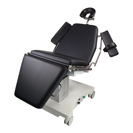
- Page 1 Mobiler Operationsstuhl Mobile Surgical Chair SC 5010 HS / ES Gebrauchsanweisung User Manual...
-
Page 2: Table Of Contents
ELEKTRISCHE ANSCHLÜSSE ....................7 GERÄTEBESCHREIBUNG UND BEDIENELEMENTE ..............8 7.1. (100-925) ..........................8 ATTERIE 7.2. (100-924) ....................... 8 ADESTATION ATTERIE 7.3. SC 5010 HS / ES OP - S ..................8 ATTERIEHALTER AM TUHL 7.4..................... 9 LEKTRISCHE NTRIEBE UND TEUEREINHEIT 7.5. - Page 3 FEHLERSUCHE ........................23 HERSTELLER ........................23 CE KENNZEICHNUNG ......................23 275g001d_SC5010_HS_3rd ed.docx 11.01.22 Seite 3 von 23...
-
Page 4: Allgemeine Angaben
1. Allgemeine Angaben Die Kenntnis dieser Gebrauchsanweisung ist für die Bedienung des SC 5010 HS / ES Operationsstuh- les erforderlich. Bitte machen Sie sich deshalb mit dem Inhalt vertraut und befolgen Sie besonders die Hinweise, die den sicheren Umgang mit dem Gerät betreffen. -
Page 5: Voraussetzungen Für Den Sicheren Betrieb
Gegenwart von brennbaren Narkosemitteln und flüchtigen Lösungsmitteln wie Alko- hol, Benzin oder ähnlichem ist, bis auf Kleinstmengen, untersagt. o Der SC 5010 HS / ES darf nicht in feuchten Räumen und keinesfalls in Räumen mit Tropf-, Schwall- oder Spritzwasser stationiert werden. -
Page 6: Produktlebensdauer Und Gewährleistungsbedingungen
Dieses Produkt darf nur unter Einhaltung der Vorgaben für den be- Allgemeine stimmungsgemäßen Gebrauch und den Umweltbedingungen, be- Gefährdung schrieben im Kapitel “Umweltbedingungen” betrieben werden. 3. Lieferumfang Die Lieferung des SC 5010 HS / ES beinhaltet folgende Positionen Position Anzahl SC 5010 HS / ES Bedientastatur Ladestation mit Anschlusskabel Batterie Qualitäts- Test Bericht... -
Page 7: Bestimmungsgemäßer Gebrauch
Der SC 5010 HS / ES Operationsstuhl ist für Untersuchungen und operative Eingriffe am Menschen bestimmt. Eine andere Verwendung als die angegebene ist nicht zulässig. o Der SC 5010 HS / ES ist für eine max. Last von 200 kg (EN 60601-2-46 Besondere Festlegung für die Sicherheit von Operationstischen) ausgelegt. -
Page 8: Gerätebeschreibung Und Bedienelemente
7. Gerätebeschreibung und Bedienelemente 7.1. Batterie (100-925) Alle elektrischen Motoren der SC 5010 HS / ES werden durch eine wiederaufladbare Batterie ange- trieben. Die Batterie bietet eine Kapazität von ca. 40 Operationen pro Ladezyklus unter einem typi- schen Belastungsprofil. Siehe auch Kapitel „Geräteentsorgung“. Die Kapazität der Batterie wird auf der Handbedienung angezeigt (s. -
Page 9: Elektrische Antriebe Und Steuereinheit
7.4. Elektrische Antriebe und Steuereinheit Der SC 5010 HS / ES Stuhl wird mit Niedervoltmotoren angetrieben. Die Steuereinheit befindet sich im Sitzrahmengestell unter dem Sitzpolster. 7.5. Bedienelemente Tastatur Die Tastatur ist mit einem Spiralkabel an die Steuereinheit unter der Abdeckung am unteren Rahmen angeschlossen. -
Page 10: Bedienelemente Fußschalter (275.012400 Optional)
7.6. Bedienelemente Fußschalter (275.012400 optional) Der Fußschalter ist mit Hilfe eines Halteblechs fest an dem Stuhl montiert. Er kann allerdings aus dem Halteblech herausgenommen werden und somit nach Bedarf auf dem Fußboden gelegt werden. Sitzhöhe ab Rückenlehne auf Rückenlehne ab Sitzhöhe auf 7.7. -
Page 11: Bedienhebel Fahrwerk
7.8. Bedienhebel Fahrwerk Der Operationsstuhl ist mit 4 Leichtlaufrol- len ausgerüstet. Die Rollen können über den zentralen Fußhebel in drei Stellungen gerastet werden. folgende Rastungen sind verfügbar o alle Räder frei und rotierend o alle Räder frei und 1 Rad verriegelt zum Lenken o alle Räder gebremst. -
Page 12: Bedienung Des Op-Stuhles
8. Bedienung des OP-Stuhles 8.1. Dauerbetrieb der Motoren Die elektrischen Motoren sind für einen Kurzzeitbetrieb von maximal. 6 Minuten Dauer ausgelegt. Eine längere Betriebszeit kann zur Überhitzung und einer dauerhaften Schädigung des Transforma- tors führen. 8.1.1. akustisches und visuelles Signal, Ladezustand der Batterie Ab 80% Entladungszustand der Batterien ertönt während des Betriebes der Motoren ein Piepton. -
Page 13: Elektrische Einstellmöglichkeiten
8.2. Elektrische Einstellmöglichkeiten Durch Betätigen der jeweiligen Taste können die Höhe, die Rückenlehne, die Fußstütze die Sitzfläche und die Kopfstütze elektrisch verstellt werden. 8.2.1. Einstellung der Höhe Durch Betätigen der Taste für die Höhenverstellung lässt sich der Stuhl stufenlos zwischen minimaler und maximaler Höhe verstellen. -
Page 14: Einstellung Der Fußstütze
8.2.3. Einstellung der Fußstütze Durch Betätigen der entsprechenden Tasten auf der Tastatur kann die Fußstütze in die gewünschte Position gefahren werden. 8.2.4. Einstellung der Sitzfläche Durch Betätigen der entsprechenden Tasten auf der Tastatur kann die Sitzfläche in die gewünschte Position gefahren werden. 275g001d_SC5010_HS_3rd ed.docx 11.01.22 Seite 14 von 23... -
Page 15: Einstellung Elektrischer Kopfheber
8.2.5. Einstellung elektrischer Kopfheber 275g001d_SC5010_HS_3rd ed.docx 11.01.22 Seite 15 von 23... -
Page 16: Programmierung Der Memory Tasten
8.2.6. Programmierung der Memory Tasten 8.2.6.1. 6 Memory Tasten (101-151) Zum Speichern einer Position verfahren Sie bitte folgendermaßen: 1. Den Stuhl einschließlich der Kopfstüt- ze mit dem Bedientasten in die ge- wünschte Position fahren. 2. die „S“ Taste unten links kurz drücken und loslassen, darauf muss ein 3- facher Piepton ertönen. -
Page 17: Trendelenburg
8.2.7. Trendelenburg Die Trendelenburg Position wird eingestellt entweder durch Betätigen der einzelnen Tasten für Sitz- fläche Rücken- und Beinstütze oder durch Betätigen rot umrandeten Taste. Hier ist die Schockpositi- on bereits fest abgespeichert und kann hiermit aufgerufen werden. Achtung: Aus sicherheitstechnischen und regulatorischen Gründen muss die Taste gedrückt gehalten werden, während der Stuhl in Bewegung ist. -
Page 18: Einstellungen Der Kopfstütze
8.3. Einstellungen der Kopfstütze Für den SC 5010 HS / ES werden verschiedene Kopfstützen angeboten. Mit einem universellen Adap- ter können alle Kopfstützen ohne Werkzeug in wenigen Sekunden ausgetauscht werden. 8.3.1. Einstellung der Standard Kopfstütze (241.030690) Die Kopfstütze (max. 20kg) kann mit einer zentralen Ver- riegelung sowohl im Längen-... -
Page 19: Einstellung Der Mehrgelenkskopfstütze (241.030648)
8.3.3. Einstellung der Mehrgelenkskopfstütze (241.030648) Diese optionale Kopfstütze (max. 20kg) lässt sich über mehrere Gelenke sehr genau und individuell auf den Patienten einstellen. Sie lässt sich mit mechanischen Klemmverschlüssen in der Entfernung zum Rückenteil um ca. 10 cm. verschieben und um +20° und – 20° kippen. Durch die Zweipunkt Lagerung ist der Kopf im- mer ideal unterstützt. -
Page 20: Zubehör
9. Zubehör Der SC 5010 HS/ES OP Stuhl ist entlang der Rückenlehne und Sitzfläche mit Geräteschienen für die Befestigung von Zubehörteilen wie Infusionsständer, Narkosebogen und ähnlichem ausgerüstet. Für die Befestigung solcher Zubehörteile den Spannkloben auf sicheren Sitz prüfen. Max.10kg Mehrgelenksarmlehne (241.030250) -
Page 21: Gerätepflege / Verschmutzungsschutz
Desinfektionsmittel dürfen eine Konzentration der Inhaltsstoffe Propanol=35% und Ethanol=25% nicht überschreiten. o Der SC 5010 HS / ES Operationsstuhl ist nicht sterilisierfähig. o Die Reinigung der Lackoberflächen erfolgt mit einem feuchten (nicht nassem) Tuch, bei hart- näckigen Verschmutzungen nicht schleifende und nicht aggressive Reinigungsmittel verwen- den. -
Page 22: Technische Daten
Depth seat cushion SC 5010 ES (eye surgery) Max. Länge Rückenlehne waagerecht Max. length chair, back rest horizon- 2050 SC 5010 HS (head surgery) Max. Länge Rückenlehne waagerecht Max. length chair, back rest horizon- 1850 Patientengewicht maximal Max. patient weight 200/300 Masse (abhängig von Optionen) ca. -
Page 23: Umweltbedingungen
Ladegerät Ladelampe Ladegerät defekt Kundendienst rufen leuchtet nicht Mechanische Beschädi- Äußere Gewalt Kundendienst rufen gungen 17. Hersteller AKRUS GmbH & Co KG Otto-Hahn-Straße 3 D-25337 ELMSHORN int. +49 (0) 4121 791930 Email: info@akrus.de FAX int. +49 (0) 4121 791939 Website : www.akrus.de... - Page 25 Mobile Surgical Chair SC 5010 HS / ES User Manual...
- Page 26 ELECTRICAL CONNECTIONS ........................6 PRODUCT DESCRIPTION AND CONTROLS ....................6 (100-925) ........................... 6 ATTERY (100-924) ......................6 ATTERY RE CHARGER UNIT SC 5010 HS / ES ................... 7 ATTERY HOLDER ON THE CHAIR ......................8 LECTRIC ACTUATORS AND CONTROL UNIT ..........................
- Page 27 MANUFACTURER ............................ 22 General To safely operate and control the SC 5010 HS / ES please carefully read this user manual before operating. Please pay attention to all cautionary statements pertaining to the safe operation of the SC 5010 SEK. Please keep the manual on file at all times while the product is in service.
- Page 28 User instructions for safe operation Before using this medical device, please carefully read and observe the safety instructions and recommendations listed in this manual Caution The device may only be installed, operated, used and maintained by Risk of persons who have been properly trained or who have the required operating knowledge and experience to do so.
- Page 29 Hazards chapter “Ambient conditions” Scope of delivery The SC 5010 HS / ES scope of delivery comprises Position SC 5010 HS / ES examination chair Re charger unit incl. power cord...
- Page 30 Mounting and commissioning The medical device is delivered completely assembled. If optional parts or accessories are part of the delivery, please refer to the respective section in this user manual for mounting or connecting instructions. No additional assembly or calibration work is required to operate the medical device. Electrical connections Warning The medical device is only de-energized when the mains plug has been...
- Page 31 Battery holder on the SC 5010 HS / ES chair The battery holder is located under the seatframe and easily accessible. Gently pull at the handle at the head end of the battery to unlock and remove battery from holder. To insert battery in holder, slide battery in position applying a gentle push on battery and wait for the audible click.
- Page 32 Electric actuators and control unit The SC 5010 HS / ES is powered by low voltage actuators. The electronic control unit is located in the lower frame section under the cover. Handheld control panel The hand held control panel is connected with a helix cable to the control unit under the cover on the lower frame.
- Page 33 Footswitch (275.012400 option) The footswitch is firmly mounted to the basic frame by means of a retaining plate. However, it can be taken out of the holding plate and are thus placed as required on the floor. Back rest up Seat high down Back rest down Seat high up...
- Page 34 Control lever for heavy duty castors The chair features 4 heavy-duty castors. The brakes are controlled two foot levers on either side of the lower frame. The three settings below are available All wheels locked (kick on black arm) All wheels unlocked and swiveling (set arms horizontal) All wheel unlocked, one wheel set for steering (kick on green arm) Foot operated control lever in different settings all wheels unlocked...
- Page 35 Operation of chair Duty cycle (continuous operation) of electrical motors The electrical motors are designed for a duty cycle of approximately 6 minutes at full load. Continuous operations exceeding that time period may cause overheat conditions and permanent damage to the transformer. 8.1.1 acoustic and visual signal, Battery charge status After discharging the battery down to approximately 20% of total capacity, the control unit will...
- Page 36 Electric controls To adjust chair height, back rest, foot rest, seat cushion tilt and head rest push the corresponding button on the control panel or foot control switches. 8.2.1 Adjustment of chair height By pushing the corresponding Buttons the chair height is infinitely adjustable between min. and max. height.
- Page 37 8.2.3 Adjustment of foot rest By pushing the corresponding buttons the foot rest is infinitely adjustable from vertical to horizontal. 8.2.4 Adjustment of seat cushion tilt The product features an electrically actuated seat section tilt. By pushing the respective button on the handheld control panel the seat cushion can be moved to the desired position.
- Page 38 8.2.5 Electric adjustment of head rest 275g001e_SC5010_HS_ES_3rd ed.docx 2022-01-11 Page 14 of 22...
- Page 39 8.2.6 Programmable memory buttons 8.2.6.1 3 memory positions (101-151) To enter a memory position please follow the steps below: 1. drive the chair including the headrest to the desired position. 2. Now briefly click and release the “S” button “bottom left”. Note the audible triple beep.
- Page 40 8.2.7 Trendelenburg The Trendelenburg position is set either by pressing the individual buttons for seat backrest and leg rest, or by pressing red outlined button. Here is the shock position already stored and can be called. Caution: For safety reasons and as a regulatory requirement the key need to be pressed and held while the chair is in motion.
- Page 41 Adjustment of head rests Various different head rests and head supports are available for the SC 5010 SEK. All head rests can be mounted or changed, without the need for any tools, within seconds. 8.3.1 Standard head rest (241.030690) central lock bolt controls both, the length...
- Page 42 8.3.3 Adjustment of multi articulated head rest (241.030648) The two cushioned bars headrest (max. 20kg (44 lbs)) assures an optimal head support at all times. The distance between the visco- elastic foam bars is individually adjustable by a clamp lock and perfectly supports any head size. By briefly opening the lock bolt, the head of the patient will automatically move the self leveling cushioned bars into a very comfortable position...
- Page 43 Accessories The SC 5010 features stainless steel side rails alongside the backrest and the seat cushion to attach certain accessories. Make sure to secure blocks properly when attaching any equipment to the side rails. (max. 10kg (22 lbs)) Arm rest Multi articulated (241.030250) Make sure, the tips of the armrests will not collide with the side rails when moving the backrest to a fully vertical position.
- Page 44 10 Cleaning and contamination protection o Contamination protection In order to protect the product against contamination by liquids, body liquids or other unwanted substances it is recommended to, while in use, cover the product with a non sterile disposable impermeable cover sheet. o Surfaces are resistant to all commonly used disinfectants as listed in the D G H M (Deutsche Gesellschaft fuer Hygiene und Mikrobiologie) list.
- Page 45 Depth seat cushion SC 5010 ES (eye surgery) Max. Länge Rückenlehne waagerecht Max. length chair, back rest 2050 horizontal SC 5010 HS (head surgery) Max. Länge Rückenlehne waagerecht Max. length chair, back rest 1850 horizontal Patientengewicht maximal Max. patient weight 200/300 Masse (abhängig von Optionen) ca.
- Page 46 Call service 17 CE conformity We declare the compliance of the device with the requirements of the Council Directive 93/42/EEC about Medical Devices 18 Manufacturer AKRUS GmbH & Co KG Otto-Hahn-Straße 3 D-25337 ELMSHORN int. +49 (0) 4121 791930 Email: info@akrus.de...
Need help?
Do you have a question about the SC 5010 HS and is the answer not in the manual?
Questions and answers