Table of Contents
Advertisement
Available languages
Available languages
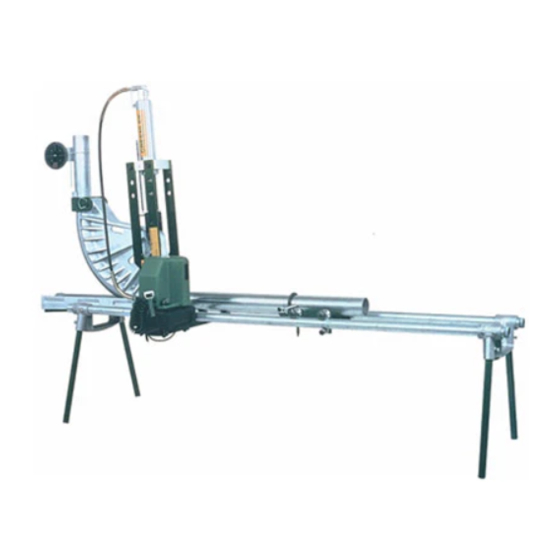
881 and 881CT Cam Track
Hydraulic Benders
99980711
INSTRUCTION MANUAL
and 1813 Bending Table
Read and understand all of the instructions and
safety information in this manual before operating
or servicing this tool.
Register this product at www.greenlee.com
© 2020 Greenlee Tools, Inc.
Español ............... 33
Français .............. 65
®
IM 981 REV 20 03/20
Advertisement
Chapters
Table of Contents

Related Manuals for Greenlee Cam Track 881


Summary of Contents for Greenlee Cam Track 881
- Page 1 Hydraulic Benders and 1813 Bending Table Read and understand all of the instructions and safety information in this manual before operating or servicing this tool. Register this product at www.greenlee.com 99980711 © 2020 Greenlee Tools, Inc. IM 981 REV 20 03/20...
-
Page 2: Table Of Contents
Important Safety Information ........3–4 conduit or pipe. Identification—Major Components ....... 5 The bender is to be coupled to any Greenlee hydraulic Assembly and Operation Instructions ......6–20 pump capable of developing 10,000 psi with a usable oil 881 and 881CT Floor Operation ......6–9 volume of 6 quarts or more. -
Page 3: Important Safety Information
881 and 881CT Hydraulic Benders IMPORTANT SAFETY INFORMATION SAFETY ALERT Use only Greenlee shoes and components when operating this bender. Other manufacturers’ shoes SYMBOL and components may fail during operation, propelling broken parts with great force. Failure to observe this warning could result in severe This symbol is used to call your attention to hazards injury or death. - Page 4 Inspect the bender, pump, and hose before each Loose clothing could get caught in moving parts. use. Replace damaged, worn, or missing parts with Greenlee replacement parts; a damaged or worn Failure to observe this warning could result in severe component may fail and strike nearby personnel.
-
Page 5: Identification-Major Components
1813 Bending Table Ram Positioner (33) Pipe Vise Unit (38) Leg Support Unit (23) Pipe Clamp (34) Pump Table Support (26) Bender Mounting Unit (27) Leg (25) Greenlee Tools, Inc. 4455 Boeing Dr. • Rockford, IL 61109-2988 USA • 815-397-7070... -
Page 6: Assembly And Operation Instructions
Decals face outward 3. Repeat Step 2 for the other connecting bar. 5. Attach the yoke (B) to the ram with the spring clip (H). Greenlee Tools, Inc. 4455 Boeing Dr. • Rockford, IL 61109-2988 USA • 815-397-7070... -
Page 7: And 881Ct Floor Operation
(E). 9. Reinsert the hitch pin clip into the roller shaft. 7. Remove one hitch pin clip from the roller shaft. Greenlee Tools, Inc. 4455 Boeing Dr. • Rockford, IL 61109-2988 USA • 815-397-7070... - Page 8 Assembly and Operation Instructions 881 and 881CT—Floor Operation (cont’d) Follow the instructions and safety information supplied with your hydraulic pump. The instructions provided here apply to Greenlee 960 (shown in the illustrations) and 980 (not shown) hydraulic pumps only. Bending Mark 10.
- Page 9 18. Release the hydraulic pressure. The ram will retract. 16. 60° of bend. 19. Remove the saddle pin. 17. 90° of bend. 20. The 90° bend is complete. Greenlee Tools, Inc. 4455 Boeing Dr. • Rockford, IL 61109-2988 USA • 815-397-7070...
-
Page 10: And 881Ct With 1813 Bending Table
6. Position the bender mounting unit (27) as shown, and slide it, tabs first, onto the two 10-foot conduits. 3. Repeat Step 2 for the other connecting bar. Greenlee Tools, Inc. 4455 Boeing Dr. • Rockford, IL 61109-2988 USA • 815-397-7070... - Page 11 10-foot conduits. Set the pipe clamps 5" and 12" from the bender mounting unit. Mount the pump supports (26) onto the clamps. Do not tighten the clamps. Greenlee Tools, Inc. 4455 Boeing Dr. • Rockford, IL 61109-2988 USA • 815-397-7070...
- Page 12 Bracket 13. Remove the rubber feet/casters from the pump. Attach the pump bracket (64) to the pump with the pump bracket mounting hardware (40–43). See illustration. Greenlee Tools, Inc. 4455 Boeing Dr. • Rockford, IL 61109-2988 USA • 815-397-7070...
- Page 13 21. Attach the hydraulic fitting unit (29) to the ram, and connect the hose to the fitting unit. Set the cylinder and yoke unit on the follow bar. Rotate the pump control lever counterclockwise. Greenlee Tools, Inc. 4455 Boeing Dr. • Rockford, IL 61109-2988 USA • 815-397-7070...
- Page 14 Secure the yoke pin with a hitch pin clip (E). 23. Insert one cylinder block pin (F) into the hole marked 24 and 25. Swing the ram unit into position. 3" CONDUIT as shown. Greenlee Tools, Inc. 4455 Boeing Dr. • Rockford, IL 61109-2988 USA • 815-397-7070...
- Page 15 Saddle Pin 29. Load the shoe into the bender with the saddle pin hole to the left, as shown. 27. Remove the yoke pin from the ram positioner. Greenlee Tools, Inc. 4455 Boeing Dr. • Rockford, IL 61109-2988 USA • 815-397-7070...
- Page 16 34. Insert the conduit to be bent. Rotate the pump control lever counterclockwise and advance the shoe until it nearly contacts the conduit. 32. Rotate the pump control lever clockwise to retract the ram. Greenlee Tools, Inc. 4455 Boeing Dr. • Rockford, IL 61109-2988 USA • 815-397-7070...
- Page 17 Attach the model 1805 Bending shoe back for the assembly of the saddle and pin. Degree Indicator (35) to the conduit. Zero the indica- tor by rotating the degree wheel. Greenlee Tools, Inc. 4455 Boeing Dr. • Rockford, IL 61109-2988 USA • 815-397-7070...
- Page 18 41. Activate the hydraulic pump to begin the bend. 44. 45° of bend. 42. 15° of bend. 45. 60° of bend. 43. 30° of bend. 46. 75° of bend. Greenlee Tools, Inc. 4455 Boeing Dr. • Rockford, IL 61109-2988 USA • 815-397-7070...
- Page 19 48. Remove the 1805 Bending Degree Indicator. 51. Remove the saddle pin and saddle. 49. Rotate the pump control lever clockwise to retract 52. Release the vise chain. the shoe. Greenlee Tools, Inc. 4455 Boeing Dr. • Rockford, IL 61109-2988 USA • 815-397-7070...
- Page 20 881 and 881CT with 1813 Bending Table (cont’d) 53. Remove the conduit from the bender. 56. To change the follow bar, twist and remove. 54 and 55. The 90° bend is complete. Greenlee Tools, Inc. 4455 Boeing Dr. • Rockford, IL 61109-2988 USA • 815-397-7070...
-
Page 21: Glossary Of Bending Terms
14. stub—same as rise 7. 90° bend—any bend that changes 15. stub-up—same as rise the direction of the conduit or pipe by 90 degrees Greenlee Tools, Inc. 4455 Boeing Dr. • Rockford, IL 61109-2988 USA • 815-397-7070... -
Page 22: Laying Out One-Shot 90° Bends
Minimum Distance from End of Conduit 2-1/2 3-1/2 IMC–RIGID Deduct 21-1/2 24-1/4 28-1/4 32-1/2 Minimum Stub Length 26-3/4 30-3/4 Minimum Distance from End of Conduit 2-1/2 2-1/2 2-1/2 2-1/2 Greenlee Tools, Inc. 4455 Boeing Dr. • Rockford, IL 61109-2988 USA • 815-397-7070... - Page 23 45° 7-1/8 6-15/16 6-1/4 6-1/8 10-1/8 8-1/4 60° 8-1/2 8-7/16 7-3/4 7-3/4 See Table 4 See Table 4 90° 11-5/8 10-3/4 See Table 4 See Table 4 Greenlee Tools, Inc. 4455 Boeing Dr. • Rockford, IL 61109-2988 USA • 815-397-7070...
- Page 24 MARK This Shoe NO. 1 NO. 2 Matches Profile Long (over 36") Follow Bar with Side Pockets This Shoe Matches Profile Short Follow Bar with Smooth Sides Greenlee Tools, Inc. 4455 Boeing Dr. • Rockford, IL 61109-2988 USA • 815-397-7070...
-
Page 25: Laying Out Bends
5. The number shown at the intersection of row L1 and the appropriate H column is L1. Place the second bending mark L1 inches from the first bending mark. 6. Bend the conduit. Greenlee Tools, Inc. 4455 Boeing Dr. • Rockford, IL 61109-2988 USA • 815-397-7070... -
Page 26: Saddles
6. In the same column, find the row labeled L2. Place the third bending mark L2 inches from the second bending mark. 7. Bend the conduit. Greenlee Tools, Inc. 4455 Boeing Dr. • Rockford, IL 61109-2988 USA • 815-397-7070... -
Page 27: U-Bends
8. Bend the conduit. 7. Make the final bending mark L1 inches from the third bending mark. 8. Bend the conduit. Greenlee Tools, Inc. 4455 Boeing Dr. • Rockford, IL 61109-2988 USA • 815-397-7070... -
Page 28: Special Bending Information Chart
MINIMUM H = 21.48 90.00 0.00 6.00 12.00 18.00 24.00 36.00 90.00 34.93 40.93 52.93 90.00 60.81 66.81 78.81 90.00 38.73 38.73 38.73 MINIMUM H = 38.73 Greenlee Tools, Inc. 4455 Boeing Dr. • Rockford, IL 61109-2988 USA • 815-397-7070... - Page 29 75.63 89.49 60.00 50.65 54.11 57.57 61.04 67.97 MINIMUM H = 28.86 90.00 3.75 9.75 15.75 27.75 90.00 50.77 90.00 84.54 90.00 51.50 MINIMUM H = 51.5 Greenlee Tools, Inc. 4455 Boeing Dr. • Rockford, IL 61109-2988 USA • 815-397-7070...
- Page 30 59.67 MINIMUM H = 21.68 90.00 5.77 11.77 17.77 23.77 35.77 90.00 34.93 40.93 52.93 90.00 60.81 66.81 78.81 90.00 38.96 38.96 38.96 MINIMUM H = 38.96 Greenlee Tools, Inc. 4455 Boeing Dr. • Rockford, IL 61109-2988 USA • 815-397-7070...
- Page 31 75.63 89.49 60.00 50.90 54.36 57.82 61.29 68.22 MINIMUM H = 29.08 90.00 3.50 9.50 15.50 27.50 90.00 50.77 90.00 84.54 90.00 51.75 MINIMUM H = 51.75 Greenlee Tools, Inc. 4455 Boeing Dr. • Rockford, IL 61109-2988 USA • 815-397-7070...
-
Page 32: Troubleshooting
Open the pump vent. Hose couplings are not fully tightened. Tighten the hose couplings. Excessive voltage drop from long extension cord. Use a shorter or heavier extension cord. Greenlee Tools, Inc. 4455 Boeing Dr. • Rockford, IL 61109-2988 USA • 815-397-7070... -
Page 33: Spanish
Lea y entienda todas las instrucciones y la información sobre seguridad que aparecen en este manual, antes de manejar esta herramienta o darle mantenimiento. Registre este producto en www.greenlee.com 99980711 © 2020 Greenlee Tools, Inc. IM 981 REV 20 03/20... -
Page 34: Descripción
Todas las especificaciones son nominales y pueden cambiar cuando se realicen mejoras en el diseño. Greenlee Tools, Inc. no será responsable por daños que resulten de la aplicación o uso indebidos de sus productos. -
Page 35: Información Importante Sobre Seguridad
IMPORTANTE INFORMACIÓN SOBRE SEGURIDAD SÍMBOLO DE ALERTA SOBRE Al accionar esta dobladora use solamente zapatas y componentes Greenlee. Las zapatas y componentes SEGURIDAD de otros fabricantes podrían fallar durante el funcionamiento, y podrían lanzar las partes rotas con gran fuerza. - Page 36 Sustituya las partes atrapada en las partes movibles. dañadas, gastadas o faltantes con piezas de repuesto Greenlee; un componente dañado o gastado puede De no observarse esta advertencia pueden sufrirse fallar y golpear al personal circundante.
-
Page 37: Identificación - Componentes Principales
Unidad de prensa para tubos (38) Unidad de apoyo de patas (23) Abrazadera para tubos (34) Apoyo de banco para bomba (26) Unidad de montaje de dobladora (27) Pata (25) Greenlee Tools, Inc. 4455 Boeing Dr. • Rockford, IL 61109-2988 USA • 815-397-7070... -
Page 38: Instrucciones De Ensamblaje Y Operación
5. Acople la horquilla (B) al cilindro con el sujetador de resorte (H). 3. Repita el paso 2 para la otra barra conectora. Greenlee Tools, Inc. 4455 Boeing Dr. • Rockford, IL 61109-2988 USA • 815-397-7070... -
Page 39: 881 Y 881Ct
9. Vuelva a introducir la chaveta de pasador de enganche en el eje del rodillo. 7. Retire una chaveta de pasador de enganche del eje del rodillo. Greenlee Tools, Inc. 4455 Boeing Dr. • Rockford, IL 61109-2988 USA • 815-397-7070... - Page 40 Siga las instrucciones y la información de seguridad suministradas con su bomba hidráulica. Las instrucciones suministradas en este manual se aplican únicamente a las bombas hidráulicas Greenlee 960 (que se muestra en las ilustraciones) y 980 (no se muestra). Marca de doblez 10.
- Page 41 18. Libere la presión hidráulica. Se retraerá el pistón. 16. 60° de doblez. 19. Retire la clavija de la silla. 17. 90° de doblez. 20. El doblez de 90° está terminado. Greenlee Tools, Inc. 4455 Boeing Dr. • Rockford, IL 61109-2988 USA • 815-397-7070...
-
Page 42: 881 Y 881Ct Con Banco De Dobladora 1813
3,05 m 3. Repita el paso 2 para la otra barra conectora. (10 pies). Greenlee Tools, Inc. 4455 Boeing Dr. • Rockford, IL 61109-2988 USA • 815-397-7070... - Page 43 13 mm (5 pulgadas) y a 305 mm (12 pulgadas) de la unidad de montaje de la dobladora. Instale los apoyos para bomba (26) sobre las abrazaderas. No apriete las abrazaderas. Greenlee Tools, Inc. 4455 Boeing Dr. • Rockford, IL 61109-2988 USA • 815-397-7070...
- Page 44 13. Quite las patas de hule/ruedecillas de la bomba. Acople la escuadra de soporte de la bomba (64) a la bomba con los herrajes de montaje de dicha escuadra (40–43). Véase la ilustración. Greenlee Tools, Inc. 4455 Boeing Dr. • Rockford, IL 61109-2988 USA • 815-397-7070...
- Page 45 21. Acople el racor hidráulico (29) al pistón, y conecte la manguera al racor. Coloque el cilindro y la horquilla en la barra seguidora. Gire a la izquierda la palanca de control de la bomba. Greenlee Tools, Inc. 4455 Boeing Dr. • Rockford, IL 61109-2988 USA • 815-397-7070...
- Page 46 23. Introduzca una clavija del bloque del cilindro (F) en 24 y 25. Gire la unidad de pistón hasta quedar en el orificio marcado 3" CONDUIT según se muestra. posición. Greenlee Tools, Inc. 4455 Boeing Dr. • Rockford, IL 61109-2988 USA • 815-397-7070...
- Page 47 27. Retire la clavija de la horquilla de la guía de posición del pistón. Greenlee Tools, Inc. 4455 Boeing Dr. • Rockford, IL 61109-2988 USA • 815-397-7070...
- Page 48 32. Gire a la derecha la palanca de control de la bomba para retraer el pistón. Greenlee Tools, Inc. 4455 Boeing Dr. • Rockford, IL 61109-2988 USA • 815-397-7070...
- Page 49 1805 (35) al tubo portacables. Gire la rueda selectora para poner a cero grados el indicador. ensamblaje de la silla y la clavija. Greenlee Tools, Inc. 4455 Boeing Dr. • Rockford, IL 61109-2988 USA • 815-397-7070...
- Page 50 41. Active la bomba hidráulica para comenzar el doblez. 44. 45° de doblez. 42. 15° de doblez. 45. 60° de doblez. 43. 30° de doblez. 46. 75° de doblez. Greenlee Tools, Inc. 4455 Boeing Dr. • Rockford, IL 61109-2988 USA • 815-397-7070...
- Page 51 51. Retire la clavija de la silla y la silla. 49. Gire a la derecha la palanca de control de la bomba 52. Libere la cadena de la prensa. para retraer la zapata. Greenlee Tools, Inc. 4455 Boeing Dr. • Rockford, IL 61109-2988 USA • 815-397-7070...
- Page 52 881 y 881CT con Banco de dobladora 1813 (continuación) 53. Retire el tubo portacables de la dobladora. 56. Para cambiar la barra seguidora, gírela y retírela. 54 y 55. El doblez de 90° está terminado. Greenlee Tools, Inc. 4455 Boeing Dr. • Rockford, IL 61109-2988 USA • 815-397-7070...
-
Page 53: Glosario De Términos De Doblado
14. Codo — lo mismo que elevación 7. Codo de 90° — cualquier doblez que cambie 90° la dirección del 15. Codo hacia arriba — lo mismo tubo portacables o tubería que elevación Greenlee Tools, Inc. 4455 Boeing Dr. • Rockford, IL 61109-2988 USA • 815-397-7070... -
Page 54: Cómo Realizar Un Doblez De 90° En Un Solo Lance
2-1/2 3-1/2 portacables IMC–RIGID Deducción 21-1/2 24-1/4 28-1/4 32-1/2 Longitud mínima del codo 26-3/4 30-3/4 Distancia mínima desde el extremo del tubo 2-1/2 2-1/2 2-1/2 2-1/2 portacables Greenlee Tools, Inc. 4455 Boeing Dr. • Rockford, IL 61109-2988 USA • 815-397-7070... -
Page 55: Tabla 3 - Carrera Del Pistón
6-1/8 10-1/8 8-1/4 60° 8-1/2 8-7/16 7-3/4 7-3/4 Véase la Tabla 4 Véase la Tabla 4 90° 11-5/8 10-3/4 Véase la Tabla 4 Véase la Tabla 4 Greenlee Tools, Inc. 4455 Boeing Dr. • Rockford, IL 61109-2988 USA • 815-397-7070... -
Page 56: Tabla 4 - Cómo Realizar Un Doblez De
Barras seguidoras largas (de más de 914 mm o 36 pulgadas) con perforaciones laterales Este perfil es compatible de zapata Barras seguidoras cortas con lados lisos Greenlee Tools, Inc. 4455 Boeing Dr. • Rockford, IL 61109-2988 USA • 815-397-7070... -
Page 57: Cómo Realizar Dobleces
L1 y la columna A apropiada es L1. Coloque la segunda marca de doblez a L1 milímetros de la primera marca de doblez. 6. Doble el tubo portacables. Greenlee Tools, Inc. 4455 Boeing Dr. • Rockford, IL 61109-2988 USA • 815-397-7070... -
Page 58: Sillas
6. En la misma columna, encuentre la fila titulada L2. Coloque la tercera marca de doblez a L2 milímetros de la segunda marca de doblez. 7. Doble el tubo portacables. Greenlee Tools, Inc. 4455 Boeing Dr. • Rockford, IL 61109-2988 USA • 815-397-7070... -
Page 59: Dobleces En U
8. Doble el tubo portacables. 7. Coloque la última marca de doblez a L1 milímetros de la tercera marca de doblez. 8. Doble el tubo portacables. Greenlee Tools, Inc. 4455 Boeing Dr. • Rockford, IL 61109-2988 USA • 815-397-7070... -
Page 60: Tabla De Información Sobre Dobleces Especiales
ALTURA MÍNIMA = 21,48 90,00 0,00 6,00 12,00 18,00 24,00 36,00 90,00 34,93 40,93 52,93 90,00 60,81 66,81 78,81 90,00 38,73 38,73 38,73 ALTURA MÍNIMA = 38,73 Greenlee Tools, Inc. 4455 Boeing Dr. • Rockford, IL 61109-2988 USA • 815-397-7070... - Page 61 75,63 89,49 60,00 50,65 54,11 57,57 61,04 67,97 ALTURA MÍNIMA = 28,86 90,00 3,75 9,75 15,75 27,75 90,00 50,77 90,00 84,54 90,00 51,50 ALTURA MÍNIMA = 51,5 Greenlee Tools, Inc. 4455 Boeing Dr. • Rockford, IL 61109-2988 USA • 815-397-7070...
- Page 62 59,67 ALTURA MÍNIMA = 21,68 90,00 5,77 11,77 17,77 23,77 35,77 90,00 34,93 40,93 52,93 90,00 60,81 66,81 78,81 90,00 38,96 38,96 38,96 ALTURA MÍNIMA = 38,96 Greenlee Tools, Inc. 4455 Boeing Dr. • Rockford, IL 61109-2988 USA • 815-397-7070...
- Page 63 75,63 89,49 60,00 50,90 54,36 57,82 61,29 68,22 ALTURA MÍNIMA = 29,08 90,00 3,50 9,50 15,50 27,50 90,00 50,77 90,00 84,54 90,00 51,75 ALTURA MÍNIMA = 51,75 Greenlee Tools, Inc. 4455 Boeing Dr. • Rockford, IL 61109-2988 USA • 815-397-7070...
-
Page 64: Solución De Problemas
Apriete los acoples de manguera. completamente apretados. La caída de voltaje es excesiva debido a la Use una extensión eléctrica más corta o longitud excesiva del cordón eléctrico. de mayor calibre. Greenlee Tools, Inc. 4455 Boeing Dr. • Rockford, IL 61109-2988 USA • 815-397-7070... -
Page 65: French
Nous vous conseillons de lire attentivement et de bien comprendre les instructions suivantes avant d’utiliser ou de procéder à l’entretien de cet outil. Enregistrez votre produit en ligne, www.greenlee.com 99980711 © 2019 Greenlee Tools, Inc. IM 981 REV 19 01/19... -
Page 66: Description
On peut obtenir des exemplaires gratuits sur simple demande www.greenlee.com. Toutes les spécifications sont nominales et peuvent changer avec l’amélioration de la conception. Greenlee Tools, Inc. ne peut être tenue responsable des dommages résultant d’une application inappropriée ou d’un mauvais usage de ses produits. -
Page 67: Informations De Sécurité Importantes
CONSIGNES DE SÉCURITÉ IMPORTANTES SYMBOLE Utiliser exclusivement des sabots et autres pièces D’AVERTISSEMENT Greenlee avec cette cintreuse. Les sabots et pièces d’autres marques peuvent subir une défaillance durant la marche et projeter des pièces cassées avec une très grande force. - Page 68 Greenlee ; un organe Le non-respect de cette mise en garde peut entraîner endommagé ou usé peut subir une défaillance et des blessures graves.
-
Page 69: Identification - Éléments Principaux
Table de cintrage 1813 Guide de vérin (33) Étau à tuyau (38) Support de pieds (23) Collier de serrage (34) Support de pompe (26) Monture de cintreuse (27) Pied (25) Greenlee Tools, Inc. 4455 Boeing Dr. • Rockford, IL 61109-2988 USA • 815-397-7070... -
Page 70: Instructions D'assemblage Et D'utilisation
Autocollants vers l'extérieur 3. Répéter l’étape 2 pour l’autre barre de 5. Attacher la chape (B) au vérin à l’aide de la goupille raccordement. élastique (H). Greenlee Tools, Inc. 4455 Boeing Dr. • Rockford, IL 61109-2988 USA • 815-397-7070... -
Page 71: Et 881Ct - Utilisation Sur Le Sol
(E) 9. Remettre la goupille beta en place dans l’axe du galet. 7. Déposer une goupille beta de l’axe du galet. Greenlee Tools, Inc. 4455 Boeing Dr. • Rockford, IL 61109-2988 USA • 815-397-7070... - Page 72 881 et 881CT — Utilisation sur le sol (suite) Suivre les instructions et les mesures de sécurité fournies avec la pompe hydraulique. Les présentes instructions s’appliquent aux pompes hydrauliques Greenlee 960 (représentée sur les illustrations) et 980 (non représentée) uniquement. Repère de cintrage 10.
- Page 73 18. Relâcher la pression hydraulique. Le vérin se rétracte. 16. Cintre de 60°. 19. Extraire la broche d’étrier. 17. Cintre de 90°. 20. Le cintrage de 90° est terminé. Greenlee Tools, Inc. 4455 Boeing Dr. • Rockford, IL 61109-2988 USA • 815-397-7070...
-
Page 74: And 881Ct Avec Table De Cintrage 1813
6. Placer la monture de cintreuse (27) comme sur l’illustration et l’enfiler, pattes d’abord, sur les deux 3. Répéter l’étape 2 pour l’autre barre de conduits de 10 pieds. raccordement. Greenlee Tools, Inc. 4455 Boeing Dr. • Rockford, IL 61109-2988 USA • 815-397-7070... - Page 75 10 pieds. Placer les colliers de serrage à 5 po et 12 po de la monture de cintreuse. Monter les supports de pompe (26) sur les colliers. Ne pas serrer les colliers. Greenlee Tools, Inc. 4455 Boeing Dr. • Rockford, IL 61109-2988 USA • 815-397-7070...
- Page 76 13. Déposer les pieds en caoutchouc/roulettes de la pompe. Fixer l’attache de pompe (64) à la pompe à l’aide de la visserie de fixation d’attache de pompe (40–43). Voir l’illustration. Greenlee Tools, Inc. 4455 Boeing Dr. • Rockford, IL 61109-2988 USA • 815-397-7070...
- Page 77 Placer le cylindre de vérin et la chape sur le rail suiveur. Tourner le levier de commande de la pompe dans le sens inverse des aiguilles d’une montre. Greenlee Tools, Inc. 4455 Boeing Dr. • Rockford, IL 61109-2988 USA • 815-397-7070...
- Page 78 23. Enfiler une broche de bloc cylindre (F) dans le trou 24 et 25. Basculer le vérin pour le mettre en position. marqué 3" CONDUIT comme sur l’illustration. Greenlee Tools, Inc. 4455 Boeing Dr. • Rockford, IL 61109-2988 USA • 815-397-7070...
- Page 79 29. Charger le sabot dans la cintreuse avec le trou de la broche d’étrier sur la gauche, comme sur l’illustration. 27. Extraire la broche de chape du guide de vérin. Greenlee Tools, Inc. 4455 Boeing Dr. • Rockford, IL 61109-2988 USA • 815-397-7070...
- Page 80 32. Tourner le levier de commande de pompe dans le sens des aiguilles d’une montre pour rétracter le vérin. Greenlee Tools, Inc. 4455 Boeing Dr. • Rockford, IL 61109-2988 USA • 815-397-7070...
- Page 81 1805 (35) au conduit. Mettre l’indicateur à pour attacher l’étrier et la broche. zéro en tournant la molette d’angle. Greenlee Tools, Inc. 4455 Boeing Dr. • Rockford, IL 61109-2988 USA • 815-397-7070...
- Page 82 41. Activer la pompe hydraulique pour débuter le 44. Cintre de 45°. cintrage. 42. Cintre de 15°. 45. Cintre de 60°. 43. Cintre de 30°. 46. Cintre de 75°. Greenlee Tools, Inc. 4455 Boeing Dr. • Rockford, IL 61109-2988 USA • 815-397-7070...
- Page 83 51. Déposer la broche d’étrier et l’étrier. 49. Tourner le levier de commande de pompe dans le 52. Desserrer la chaîne de l’étau. sens des aiguilles d’une montre pour rétracter le sabot. Greenlee Tools, Inc. 4455 Boeing Dr. • Rockford, IL 61109-2988 USA • 815-397-7070...
- Page 84 53. Enlever le conduit de la cintreuse. 56. Pour changer de rail suiveur, le pivoter et le déposer. 54 et 55. Le cintrage de 90° est terminé. Greenlee Tools, Inc. 4455 Boeing Dr. • Rockford, IL 61109-2988 USA • 815-397-7070...
-
Page 85: Glossaire Des Termes De Cintrage
15. colonne montante — synonyme 7. coude à 90° — tout coude qui d’élévation change la direction du conduit ou tuyau de 90 degrés Greenlee Tools, Inc. 4455 Boeing Dr. • Rockford, IL 61109-2988 USA • 815-397-7070... -
Page 86: Préparer Des Cintrages À 90° En Un Coup
36-1/4 Distance minimale depuis l’extrémité 2-1/2 3-1/2 IMC–RIGIDE Déduction 21-1/2 24-1/4 28-1/4 32-1/2 Longueur de colonne minimale 26-3/4 30-3/4 Distance minimale depuis l’extrémité 2-1/2 2-1/2 2-1/2 2-1/2 Greenlee Tools, Inc. 4455 Boeing Dr. • Rockford, IL 61109-2988 USA • 815-397-7070... - Page 87 45° 7-1/8 6-15/16 6-1/4 6-1/8 10-1/8 8-1/4 60° 8-1/2 8-7/16 7-3/4 7-3/4 Voir Table 4 Voir Table 4 90° 11-5/8 10-3/4 Voir Table 4 Voir Table 4 Greenlee Tools, Inc. 4455 Boeing Dr. • Rockford, IL 61109-2988 USA • 815-397-7070...
- Page 88 Correspond DÉDUCTION de sabot Rail suiveur long REPÈRE REPÈRE (plus de 36 po) à évidements latéraux Ce profil Correspond de sabot Rail suiveur court à côtés lisses Greenlee Tools, Inc. 4455 Boeing Dr. • Rockford, IL 61109-2988 USA • 815-397-7070...
-
Page 89: Préparation Des Cintrages
H correcte est la valeur L1. Placer le deuxième repère de cintrage à L1 pouces du premier repère de cintrage. 6. Cintrer le conduit. Greenlee Tools, Inc. 4455 Boeing Dr. • Rockford, IL 61109-2988 USA • 815-397-7070... -
Page 90: Dos D'ânes
6. Dans la même colonne, se reporter à la ligne marquée L2. Placer le troisième repère de cintrage à L2 pouces du deuxième repère de cintrage. 7. Cintrer le conduit. Greenlee Tools, Inc. 4455 Boeing Dr. • Rockford, IL 61109-2988 USA • 815-397-7070... -
Page 91: Cintrages En U
8. Cintrer le conduit. cintrage. 7. Placer le dernier repère de cintrage à L1 pouces du troisième repère de cintrage. 8. Cintrer le conduit. Greenlee Tools, Inc. 4455 Boeing Dr. • Rockford, IL 61109-2988 USA • 815-397-7070... - Page 92 H MINIMUM = 21,48 90,00 0,00 6,00 12,00 18,00 24,00 36,00 90,00 34,93 40,93 52,93 90,00 60,81 66,81 78,81 90,00 38,73 38,73 38,73 H MINIMUM = 38,73 Greenlee Tools, Inc. 4455 Boeing Dr. • Rockford, IL 61109-2988 USA • 815-397-7070...
- Page 93 75,63 89,49 60,00 50,65 54,11 57,57 61,04 67,97 H MINIMUM = 28,86 90,00 3,75 9,75 15,75 27,75 90,00 50,77 90,00 84,54 90,00 51,50 H MINIMUM = 51,5 Greenlee Tools, Inc. 4455 Boeing Dr. • Rockford, IL 61109-2988 USA • 815-397-7070...
- Page 94 59,67 H MINIMUM = 21,68 90,00 5,77 11,77 17,77 23,77 35,77 90,00 34,93 40,93 52,93 90,00 60,81 66,81 78,81 90,00 38,96 38,96 38,96 H MINIMUM = 38,96 Greenlee Tools, Inc. 4455 Boeing Dr. • Rockford, IL 61109-2988 USA • 815-397-7070...
- Page 95 75,63 89,49 60,00 50,90 54,36 57,82 61,29 68,22 H MINIMUM = 29,08 90,00 3,50 9,50 15,50 27,50 90,00 50,77 90,00 84,54 90,00 51,75 H MINIMUM = 51.75 Greenlee Tools, Inc. 4455 Boeing Dr. • Rockford, IL 61109-2988 USA • 815-397-7070...
-
Page 96: Dépannage
Raccords de flexible mal serrés. Serrer les raccords de flexible. Chute de tension excessive en raison de la Utiliser un cordon électrique plus court ou longueur du cordon électrique. plus gros. Greenlee Tools, Inc. 4455 Boeing Dr. • Rockford, IL 61109-2988 USA • 815-397-7070... -
Page 97: Illustrations And Parts Lists
881 and 881CT Hydraulic Benders Illustration—Major Components of 881 and 881CT 2-1/2" Bending Group 3" Bending Group 3-1/2" Bending Group 4" Bending Group Greenlee Tools, Inc. 4455 Boeing Dr. • Rockford, IL 61109-2988 USA • 815-397-7070... - Page 98 50265873 3" saddle insert ..................1 50265857 3" saddle strap ..................1 90510887 Screw, cap ....................2 90500288 Lock washer ....................2 90526465 Lock nut ....................2 Greenlee Tools, Inc. 4455 Boeing Dr. • Rockford, IL 61109-2988 USA • 815-397-7070...
- Page 99 Bar, reinforcement, 4" ................2 90502264 Screw, cap, 5/16–18 x 1.25 socket head ..........6 50233637 Box, job ..................... 1 50302396 Set, casters (two rigid, two swivel)............1 Greenlee Tools, Inc. 4455 Boeing Dr. • Rockford, IL 61109-2988 USA • 815-397-7070...
- Page 100 881 and 881CT Hydraulic Benders Illustration—Ram (50274163) Greenlee Tools, Inc. 4455 Boeing Dr. • Rockford, IL 61109-2988 USA • 815-397-7070...
- Page 101 Packing kit, repair (includes 8, 9, 13, and 13A) Items 12 and 13 were used prior to April 1997; items 12A and 13A have been used since April 1997. Use 12A and 13A if possible. Greenlee Tools, Inc. 4455 Boeing Dr. • Rockford, IL 61109-2988 USA • 815-397-7070...
- Page 102 881 and 881CT Hydraulic Benders Illustration—1813 Bending Table (50289012) Greenlee Tools, Inc. 4455 Boeing Dr. • Rockford, IL 61109-2988 USA • 815-397-7070...
- Page 103 Screw, machine, 1/4–20 x .500 round head (for the 980 pump) ....4 90516745 Washer, lock, .259 x .489 x .062 ............... 4 90515935 Nut, hex, 1/4–20 steel (for the 960 SAPS pump) ........4 Greenlee Tools, Inc. 4455 Boeing Dr. • Rockford, IL 61109-2988 USA • 815-397-7070...
- Page 104 Decal, Greenlee ..................1 4455 Boeing Drive • Rockford, IL 61109-2988 • USA • 815-397-7070 USA Tel: 800-435-0786 Canada Tel: 800-435-0786 International Tel: +1-815-397-7070 ©2020 Greenlee Tools, Inc. • An ISO 9001 Company Fax: 800-451-2632 Fax: 800-524-2853 Fax: +1-815-397-9247 www.greenlee.com...
Need help?
Do you have a question about the Cam Track 881 and is the answer not in the manual?
Questions and answers