Greenlee 555 Instruction Manual
555 electric bender 1/2" thru 2" rigid and thin-wall emt conduit 1-1/2" and 2" imc conduit
Hide thumbs
Also See for 555:
- Instruction manual (84 pages) ,
- Service manual (26 pages) ,
- Instruction manual (84 pages)
Table of Contents
Advertisement
INSTRUCTION MANUAL
555 Electric Bender
1/2" thru 2" Rigid and Thin-Wall EMT Conduit
1-1/2" and 2" IMC Conduit
Serial Numbers PL-32216-PGJ and up
Read and understand all of the instructions and
Safety information in this manual before operating
or servicing this tool.
999 5789.2
© 2001 Greenlee Textron
IM 909 REV 18 9/01
Advertisement
Table of Contents

Related Manuals for Greenlee 555


Summary of Contents for Greenlee 555
- Page 1 INSTRUCTION MANUAL 555 Electric Bender 1/2" thru 2" Rigid and Thin-Wall EMT Conduit 1-1/2" and 2" IMC Conduit Serial Numbers PL-32216-PGJ and up Read and understand all of the instructions and safety information in this manual before operating or servicing this tool.
-
Page 2: Table Of Contents
Replacement manuals are available upon request at no charge. Description The 555 Electric Bender Power Unit is designed for use with 1/2 through 2" rigid, 1/2 through 2" EMT and 1-1/2 through 2" IMC bending attachment groups. No modifi- cation to the 555 power unit is required to accommodate these groups. -
Page 3: Important Safety Information
Using this tool in a hazardous environment can result in a fire or explosion. Failure to observe this warning will result in severe injury or death. Greenlee Textron / Subsidiary of Textron Inc. 4455 Boeing Dr., Rockford, IL 61109-2988 815/397-7070... - Page 4 Loose clothing can get caught in moving can result in severe injury or death. parts. • Inspect the bender before use. Replace worn, damaged or missing parts with Greenlee replace- ment parts. A damaged or improperly assembled component could break and strike nearby Pinch points: personnel.
-
Page 5: Grounding Instructions
Failure to observe these warnings ordinances. can result in severe injury or death. Do not use an adapter. 120-Volt Plug and Receptacle Plug Receptacle 230-Volt Plug and Receptacle Plug Receptacle Greenlee Textron / Subsidiary of Textron Inc. 4455 Boeing Dr., Rockford, IL 61109-2988 815/397-7070... -
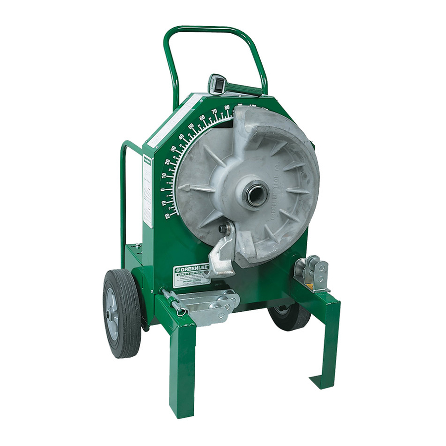
Page 6: Identification
8. Control Switch Cord 3. Control Switch 9. Electrical Control Box 4. Main Shaft 10. Gear Reductor 5. Right-hand Leg 11. Drive Motor 6. Left-hand Leg Greenlee Textron / Subsidiary of Textron Inc. 4455 Boeing Dr., Rockford, IL 61109-2988 815/397-7070... -
Page 7: Setup
Secure the support roller or unit with the quick release hinge pin (see Fig. 3). 1/2 & 3/4 1-1/4 Figure 1 Figure 3 Greenlee Textron / Subsidiary of Textron Inc. 4455 Boeing Dr., Rockford, IL 61109-2988 815/397-7070... -
Page 8: Bending Instructions
UNLOAD position. Allow shoe to rotate, drop the unit support (see Fig. 6) and remove conduit (see Figs. 7 & 8). 2" minimum Figure 4 Greenlee Textron / Subsidiary of Textron Inc. 4455 Boeing Dr., Rockford, IL 61109-2988 815/397-7070... - Page 9 555 Electric Bender Bending Instructions (cont’d) 1/2" - 2" Rigid Conduit, Schedule 40 Pipe and 1/2" - 1-1/4" EMT (cont’d) Figure 6 Figure 8 Figure 7 Greenlee Textron / Subsidiary of Textron Inc. 4455 Boeing Dr., Rockford, IL 61109-2988 815/397-7070...
- Page 10 (Fig. 10). Step on the loading peddle, raising the proper Figure 11 rollers to contact the conduit (Fig. 10). Figure 10 Greenlee Textron / Subsidiary of Textron Inc. 4455 Boeing Dr., Rockford, IL 61109-2988 815/397-7070...
- Page 11 Special Application Variation in conduit can result in wrinkling or side The 555 bender may be placed flat for special applica- marking of 1-1/2" and 2" EMT or IMC. This bender is tions where unusual bends may be required. The unit is...
- Page 12 Offset Bending in this manual. springback — the amount, measured in degrees, that a conduit or pipe tends to straighten after being bent. Greenlee Textron / Subsidiary of Textron Inc. 4455 Boeing Dr., Rockford, IL 61109-2988 815/397-7070...
- Page 13 48-3/4 96-1/4 1-1/2 18-3/4 33-3/4 48-3/4 16-1/4 31-1/4 46-1/4 61-1/4 92-1/2 17-1/2 33-3/4 48-3/4 63-3/4 48-3/4 63-3/4 96-1/4 17-1/2 33-3/4 48-3/4 63-3/4 96-1/4 Figures are approximate Greenlee Textron / Subsidiary of Textron Inc. 4455 Boeing Dr., Rockford, IL 61109-2988 815/397-7070...
- Page 14 11-5/16 14-1/8 16-15/16 19-13/16 22-5/8 25-7/16 28-1/4 31-1/8 Figures are approximate Chart D CONDUIT SIZE 1-1/4 1-1/2 “X” 3-1/16 3-1/16 3-3/16 4-1/4 4-1/2 Figures are approximate Greenlee Textron / Subsidiary of Textron Inc. 4455 Boeing Dr., Rockford, IL 61109-2988 815/397-7070...
- Page 15 555 Electric Bender Adjusting Chains The 555 bender has two chains in the power train; one is located in the rear and one in the front. New chains will stretch slightly; therefore, the front chain should be adjusted after 10 to 20 bends have been made in 1-1/2"...
-
Page 16: Special Bending Information
7. Make your first bend after placing the front edge of the shoe hook on the first mark and your second bend after placing the front edge of the shoe hook under the second mark. Greenlee Textron / Subsidiary of Textron Inc. 4455 Boeing Dr., Rockford, IL 61109-2988 815/397-7070... - Page 17 Remember to make the second bend double the angle of the first bend. Make your third bend after placing the front edge of the shoe hook on the third mark. Greenlee Textron / Subsidiary of Textron Inc. 4455 Boeing Dr., Rockford, IL 61109-2988 815/397-7070...
- Page 18 7. Make your first bend after placing the front edge of the shoe hook on the first mark and your second bend after placing the front edge of the shoe hook on the second mark. Greenlee Textron / Subsidiary of Textron Inc. 4455 Boeing Dr., Rockford, IL 61109-2988 815/397-7070...
- Page 19 MINIMUM H = 8.03 1.13 3.13 6.13 9.13 15.13 27.13 12.62 15.62 21.62 33.62 21.32 24.32 30.32 42.32 13.95 13.95 13.95 13.95 MINIMUM H = 13.95 Greenlee Textron / Subsidiary of Textron Inc. 4455 Boeing Dr., Rockford, IL 61109-2988 815/397-7070...
- Page 20 29.25 36.18 50.04 20.69 22.42 24.16 27.62 34.55 MINIMUM H = 11.92 1.88 4.88 10.88 22.88 20.13 32.13 34.29 46.29 21.38 21.38 MINIMUM H = 21.38 Greenlee Textron / Subsidiary of Textron Inc. 4455 Boeing Dr., Rockford, IL 61109-2988 815/397-7070...
- Page 21 40.55 26.21 29.67 36.60 50.46 24.40 26.14 29.60 36.53 MINIMUM H = 13.63 2.62 8.62 20.62 19.94 31.94 34.80 46.80 23.74 23.74 MINIMUM H = 23.74 Greenlee Textron / Subsidiary of Textron Inc. 4455 Boeing Dr., Rockford, IL 61109-2988 815/397-7070...
- Page 22 MINIMUM H = 7.53 1.50 3.50 6.50 9.50 15.50 27.50 13.01 16.01 22.01 34.01 20.30 23.30 29.30 41.30 12.62 12.62 12.62 12.62 MINIMUM H = 12.62 Greenlee Textron / Subsidiary of Textron Inc. 4455 Boeing Dr., Rockford, IL 61109-2988 815/397-7070...
- Page 23 27.80 34.73 48.59 20.00 21.74 23.47 26.93 33.86 MINIMUM H = 11.32 2.25 5.25 11.25 23.25 20.79 32.79 32.53 44.53 19.39 19.39 MINIMUM H = 19.39 Greenlee Textron / Subsidiary of Textron Inc. 4455 Boeing Dr., Rockford, IL 61109-2988 815/397-7070...
- Page 24 16.27 19.73 26.66 40.52 26.51 29.97 36.90 50.76 25.11 26.85 30.31 37.24 MINIMUM H = 14.25 1.87 7.87 19.87 31.80 47.16 24.72 MINIMUM H = 24.72 Greenlee Textron / Subsidiary of Textron Inc. 4455 Boeing Dr., Rockford, IL 61109-2988 815/397-7070...
- Page 25 40.55 26.21 29.67 36.60 50.46 24.19 25.93 29.39 26.32 MINIMUM H = 13.45 2.75 8.75 20.75 19.94 31.94 34.80 46.80 23.53 23.53 MINIMUM H = 23.53 Greenlee Textron / Subsidiary of Textron Inc. 4455 Boeing Dr., Rockford, IL 61109-2988 815/397-7070...
- Page 26 555 Electric Bender Exploded View — 555 Electric Bender Eff. S/N PL-32216-PGJ Greenlee Textron / Subsidiary of Textron Inc. 4455 Boeing Dr., Rockford, IL 61109-2988 815/397-7070...
- Page 27 555 Electric Bender When ordering parts give Parts List — 555 Electric Bender Serial Number of unit PART NO. DESCRIPTION QTY. No. 555 Electric Bender, 115V No. 555-22 Electric Bender, 230V 502 3424.2 Frame unit ........................1 501 8005.3 Sprocket unit #60, 80 tooth ..................... 1 905 2414.4...
- Page 28 Control box cover (not shown) ........ 1 *NOTE: For replacement of power module unit on benders preceding S/N PL-20406-L, specify 503 3351.8 Power Module Replacement Unit. Greenlee Textron / Subsidiary of Textron Inc. 4455 Boeing Dr., Rockford, IL 61109-2988 815/397-7070...
- Page 29 555 Electric Bender Electrical Amber LED Red LED Green LED Control Module 503 5411.6 Power Module 503 4140.5 Greenlee Textron / Subsidiary of Textron Inc. 4455 Boeing Dr., Rockford, IL 61109-2988 815/397-7070...
- Page 30 E. Motor lead (white) F. Motor lead (black) G. Power cord H. Motor conduit I. Circuit breaker reset lever J. Power module 503 4140.5 K. Control module 503 5411.6 Greenlee Textron / Subsidiary of Textron Inc. 4455 Boeing Dr., Rockford, IL 61109-2988 815/397-7070...
- Page 31 LED fails to light.) This red LED will also momentarily light up when either the pendant bend If the operating instructions for the 555 Bender are being and unload switches are released from the down followed, but the drive motor does not operate when...
- Page 32 1. With the power plug disconnected, remove the white the complete unit to a Greenlee authorized service and black motor leads from terminal AK1 and AK2 center for servicing. Do not unsolder components on the SCR block.
- Page 33 4. Connect the red, white, and black wires from the pendant switch to the red, white and black wires respec- tively of the 15 pin connector, using wire nuts. Greenlee Textron / Subsidiary of Textron Inc. 4455 Boeing Dr., Rockford, IL 61109-2988 815/397-7070...
- Page 34 918 2626.0 Cover screw - brush #10-32 x 1/2 round head machine ..4 918 6256.6 Brush cover ................2 918 6257.4 Brush cover insulation ............2 Greenlee Textron / Subsidiary of Textron Inc. 4455 Boeing Dr., Rockford, IL 61109-2988 815/397-7070...
- Page 35 555 Electric Bender Wiring Diagram — 115V No. 555 Electric Bender 12 GA. BLACK WHITE GREEN 120 VOLTS - 60 HZ FNM15 BLUE RECTIFIER B-CON – RECT. VAR 1 VARISTOR U-CON BLUE 14 GA. U-CON B-CON BLUE WHITE BLUE –...
- Page 36 Exploded View — Control Box Unit Eff. S/N PL2401 thru PL7571 115V and 230V systems Do not use pendant switch unit 503 6370.0 to repair this control. Greenlee Textron / Subsidiary of Textron Inc. 4455 Boeing Dr., Rockford, IL 61109-2988 815/397-7070...
- Page 37 Resistor, 230V ....................1 502 6375.7 Transformer unit, 230V (includes #90 & 95) ........... 1 918 5979.4 Fusetron, 2 AMP-FNA-2 ................. 1 * For units preceding SN PL800 Greenlee Textron / Subsidiary of Textron Inc. 4455 Boeing Dr., Rockford, IL 61109-2988 815/397-7070...
- Page 38 555 Electric Bender Wiring Diagram — 230V No. 555 Electric Bender BLACK WHITE GREEN 220 VOLTS - 50 HZ FU-1 FU-2 FNM8 FNM8 BLUE – B-CON BLACK RECT. RECTIFIER VAR 1 BLACK VARISTOR U-CON VAR 2 BLUE B-CON U-CON BLUE...
- Page 39 Washer, 3/4 x 7/16 x 1/8 Neoprene ..........1 905 1295.2 3/8-16 UNC x 1-1/2 Socket head cap screw ........1 905 2646.5 3/8-16 UNC Lock nut ............... 1 SHOE NOT AVAILABLE SEPARATELY Greenlee Textron / Subsidiary of Textron Inc. 4455 Boeing Dr., Rockford, IL 61109-2988 815/397-7070...
- Page 40 5/8 Lock washer (split ) ..............1 905 2426.8 5/8-11 UNC x 4" Socket head cap screw ........1 502 3422.6 Stud, drive ..................4 SHOE NOT AVAILABLE SEPARATELY Greenlee Textron / Subsidiary of Textron Inc. 4455 Boeing Dr., Rockford, IL 61109-2988 815/397-7070...
- Page 41 3/8-16 UNC x 1-1/4 SAE grade 5 socket head cap screw ..... 1 905 1088.7 3/8-16 UNC x 1-1/4 socket head screw .......... 1 SHOE NOT AVAILABLE SEPARATELY Greenlee Textron / Subsidiary of Textron Inc. 4455 Boeing Dr., Rockford, IL 61109-2988 815/397-7070...
- Page 42 Hook, 2" IMC ............1 501 8838.0 Pin, 2" IMC hook ............1 502 3422.6 Stud, drive ..............3 905 1528.5 Ring, Tru-Arc retaining ..........2 SHOE NOT AVAILABLE SEPARATELY Greenlee Textron / Subsidiary of Textron Inc. 4455 Boeing Dr., Rockford, IL 61109-2988 815/397-7070...
- Page 43 Screw, 7/16 - 14 UNC x 1 flat head ......2 905 3394.1 Screw, 7/16 - 14 UNC x 1 flat head ......2 * #21 must be torqued to 40 - 45 foot/pounds Greenlee Textron / Subsidiary of Textron Inc. 4455 Boeing Dr., Rockford, IL 61109-2988 815/397-7070...
- Page 44 Greenlee Textron / Subsidiary of Textron Inc. 4455 Boeing Drive, Rockford, IL 61109-2988 USA Customer Service (International): 815/397-7070 • Fax: 815/397-9247 Customer Service (North America): 800/435-0786 • USA Fax: 800/451-2632, 815/397-1865 Canada Fax: 800/524-2853 www.greenlee.textron.com Printed in the USA...
Need help?
Do you have a question about the 555 and is the answer not in the manual?
Questions and answers
Deduct for 2” rigid conduit
The deduction for 2" rigid conduit using the Greenlee 555 is 20 inches.
This answer is automatically generated