
Related Manuals for Fluke 714B/EN


Summary of Contents for Fluke 714B/EN
- Page 1 714B Thermocouple Calibrator Users Manual January 2014 © 2014 Fluke Corporation. All rights reserved. Specifications are subject to change without notice. All product names are trademarks of their respective companies.
- Page 2 LIMITED WARRANTY AND LIMITATION OF LIABILITY This Fluke product will be free from defects in material and workmanship for three years from the date of purchase. This warranty does not cover fuses, disposable batteries, or damage from accident, neglect, misuse, alteration, contamination, or abnormal conditions of operation or handling.
-
Page 3: Table Of Contents
Table of Contents Title Page Introduction ........................1 How to Contact Fluke ..................... 1 Safety Information ......................3 Safe Working Practices ....................3 Standard Equipment....................... 5 Input and Output Terminals .................... 7 Keys ..........................9 Display ........................... 11 Auto Power-Off ....................... 13 Auto Backlight-Off ...................... - Page 4 714B Users Manual Step and Ramp Modes ....................22 Auto Storage of Settings ....................22 Replace the Batteries ....................23 Maintenance ........................24 Clean the Product ..................... 24 Service Center Calibration or Repair ................ 24 Replacement Parts ....................25 Specifications ........................ 27 Thermocouple mV Input ....................
- Page 5 List of Tables Table Title Page Summary of Source and Measure Functions ................ 2 International Symbols ......................4 Input/Output Terminals and Connectors ................8 Key Functions ........................10 Elements on the Display ......................12 Thermocouple Types Accepted ..................... 16 Replacement Parts ........................ 25...
- Page 6 List of Figures Figure Title Page Standard Equipment ......................6 Input/Output Terminals and Connectors ................7 Keys ............................9 Elements of a Typical Display ....................11 Magnet Mounting with Hanging Strap ................... 14 Measure Temperature with a Thermocouple ................. 18 Connections for Simulating a Thermocouple .................
-
Page 7: Introduction
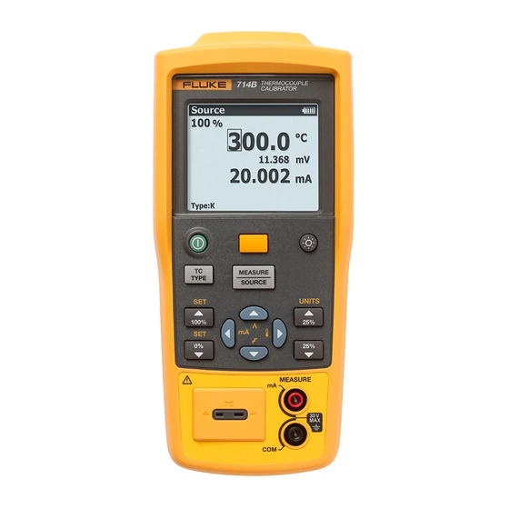
Introduction The Fluke 714B Thermocouple Calibrator (the Product) is a handheld, battery-operated instrument that measures and sources a variety of thermocouples. It also has an isolated channel to measure 4-20 mA. See Table 1. - Page 8 714B Users Manual Table 1. Summary of Source and Measure Functions Function Measure Source Thermocouple and mV Types E, J, K, T, B, R, S, L, U, N, C, BP, XK, G, D, P, M and mV Other functions Step, Ramp...
-
Page 9: Safety Information
Thermocouple Calibrator Safety Information Safety Information • Do not connect any test leads to voltages above 30 V when used with the product, A Warning identifies conditions and procedures that are even if ratings above 30 V appear on the dangerous to the user. - Page 10 Product Category: With reference to the equipment types in the WEEE Directive Annex I, this product is classed as category 9 "Monitoring and Control Instrumentation" product. Do not dispose of this product as unsorted municipal waste. Go to Fluke’s website for recycling information.
-
Page 11: Standard Equipment
TC Cap for TC hole • Mini standard TC plugs (with 80cm TC wire) package (Including Type K) • 4 AA alkaline batteries • Magnet Strap TPAK • 712B/714B Safety Sheet • 714B Quick Reference Guide • 714B Users Manual (available on Fluke’s website) - Page 12 714B Users Manual AC175 Alligator Clips TC Plugkit K Type TL75 Test Leads hrk01.eps Figure 1. Standard Equipment...
-
Page 13: Input And Output Terminals
Thermocouple Calibrator Input and Output Terminals Input and Output Terminals Figure 2 shows the input and output terminals on the Product. Table 3 explains their use. hrk02.eps Figure 2. Input/Output Terminals and Connectors... - Page 14 714B Users Manual Table 3. Input/Output Terminals and Connectors Name Description MEASURE mA , Input terminals for measuring current. terminals Terminal for measuring or simulating thermocouples. This terminal accepts a TC input/output miniature polarized thermocouple plug with flat, in-line blades spaced 7.9 mm (0.312 in) center to center.
-
Page 15: Keys
Thermocouple Calibrator Keys Keys The Product has keys for different purposes. Some keys have secondary functions that are available when SHIFT already shows on the display. Figure 3 shows the Product keys and Table 4 explains their use. hrk03.eps Figure 3. Keys... - Page 16 714B Users Manual Table 4. Key Functions Name Description Turns the power on or off. Shifts to secondary function when pushed before other keys (Shift mode). Turns backlight on or off. Increments output by 25 % of span. Secondary function: toggles between temperature units (°C or ...
-
Page 17: Display
Thermocouple Calibrator Display Display Figure 4 shows the elements of a typical display. Figure 5 describes the elements. hrk15.eps Figure 4. Elements of a Typical Display... - Page 18 714B Users Manual Table 5. Elements on the Display Item Description 100 % of value span Source or Measure mode Temperature reading Battery usage status Unit of temperature mV reading mA reading Selected TC type ...
-
Page 19: Auto Power-Off
Thermocouple Calibrator Auto Power-Off To enable the auto backlight-off mode: Auto Power-Off The Product provides an auto power-off function to save Push . power. When the auto power-off mode is enabled, the When SHIFT shows on the display, push . Product automatically powers off after 15 minutes of inactivity. -
Page 20: Magnet Mounting And Hanging Strap
714B Users Manual Magnet Mounting and Hanging Strap The Product has a magnet on the rear of the unit. It is removable. This magnet enables users to mount the Product on metal environment and free their hands. In addition, this Product has a hanging strap on the magnet. -
Page 21: Measure Ma Current
Thermocouple Calibrator Measure mA Current Measure mA Current Note One pin is wider than the other. Do not try to Caution force a miniplug in the wrong polarization.If the To prevent impact to the measurement Product and the thermocouple plug are at function, do not use the Product to measure different temperatures, wait one minute or more current near strong magnetic fields. - Page 22 714B Users Manual Table 6. Thermocouple Types Accepted Positive Lead (H) Color Positive Lead Specified Range Negative Lead Type Material (°C) Material ANSI* IEC** Chromel -250 to 1000 Purple Violet Constantan Ni-Cr-Si -200 to 1300 Orange Pink Ni-Si-Mg Iron -210 to 1200 White Black Constantan...
- Page 23 Thermocouple Calibrator Measure Temperature Table 6. Thermocouple Types Accepted (cont.) Tungsten 100 to 2315 White Tungsten - 26 % Rhenium Tungsten - 3 % Rhenium 0 to 2315 White Tungsten - 25 % Rhenium Platinel 5355 0 to 1395 Platinel 7674 Nickel –...
- Page 24 714B Users Manual Process Temperature Warning 30 V maximum to TC Miniplug hrk14.eps Figure 6. Measure Temperature with a Thermocouple...
-
Page 25: Simulate Thermocouples
Thermocouple Calibrator Simulate Thermocouples Proceed as follows to simulate a thermocouple: Simulate Thermocouples Attach the thermocouple leads to the appropriate TC Connect the Product TC input/output to the instrument miniplug, then to the TC input/output as shown in under test with thermocouple wire and the appropriate Figure 7. - Page 26 714B Users Manual TEST DC PWR – + – – TC Miniplug Color depends on type of TC hrk10.eps Figure 7. Connections for Simulating a Thermocouple...
-
Page 27: Scale Ma Channel To Temperature
Thermocouple Calibrator Scale mA Channel to Temperature Scale mA Channel to Temperature Set 0 % and 100 % Output Parameters The Product provides a function to convert mA current You must set the 0 % and 100 % points before you can channel reading to temperature reading. -
Page 28: Step And Ramp Modes
714B Users Manual Step and Ramp Modes Auto Storage of Settings The Product allows you to set Step and Ramp modes for The Product automatically stores the latest settings, easier check of points within the linear range in Source including the temperature unit, the linear range of mA mode. -
Page 29: Replace The Batteries
Thermocouple Calibrator Replace the Batteries Replace the Batteries Warning To prevent false readings, which could lead to possible electric shock or personal injury, replace the batteries as soon as the low battery indicator appears. Figure 8 shows you how to replace the batteries. hnh38.eps Figure 8. -
Page 30: Maintenance
Service Center. case, do not use solvents or abrasive cleansers. Fluke assumes no responsibility for damage in transit. To locate an authorized service center, refer to “How to Clean the Product with a soft cloth dampened with water Contact Fluke”... -
Page 31: Replacement Parts
Thermocouple Calibrator Maintenance Replacement Parts Table 7 lists the part number of each replaceable part. Refer to Figure 9. Case seal rubber 4307186 Table 7. Replacement Parts Case bottom assembly 4307079 Item Description Qty. Screw, M3, 13.5 mm, 2388382 ... - Page 32 714B Users Manual hrk46.eps Figure 9. Replacement Parts...
-
Page 33: Specifications
Thermocouple Calibrator Specifications Specifications Specifications are based on a one year calibration cycle and apply from +18 °C to +28 °C unless stated otherwise. All specifications assume a 5 minute warmup period. Thermocouple mV Input Accuracy (% of Reading + Floor) Range Resolution 1 year... -
Page 34: Thermocouple Input And Output
714B Users Manual Thermocouple Input and Output Measure (°C) Source (°C) TC Type Range 1 year 2 year 1 year 2 year -250 to 200 -200 to -100 -100 to 600 600 to 1000 -200 to -100 -100 to 900 900 to 1300 -210 to -100 -100 to 800... - Page 35 Thermocouple Calibrator Specifications -20 to 0 0 to 100 100 to 1767 -20 to 0 0 to 200 200 to 1400 1400 to 1767 0 to 800 800 to 1200 1200 to 1800 1800 to 2316 -200 to -100 -100 to 800 800 to 900 -200 to 0 0.9.
- Page 36 714B Users Manual 0 to 300 300 to 1500 1500 to 2315 0 to 1000 1000 to 1395 -50 to 100 100 to 1000 1000 to 1410 Sensor inaccuracies not included. Accuracy with external cold junction; for internal junction add 0.2 °C Temperature scale: ITS-90 Compensation: NIST Monograph 175 for B, R, S, E, J, K, N, T.
-
Page 37: General Specifications
Thermocouple Calibrator General Specifications General Specifications Maximum voltage applied between any terminal and earth ground or between 30 V any two terminals: -10 °C to 50 °C Operating temperature -20 °C to 60 °C Storage temperature Operating altitude 2,000 meters Storage altitude 12,000 meters Non condensing...
Need help?
Do you have a question about the 714B/EN and is the answer not in the manual?
Questions and answers