Table of Contents

Subscribe to Our Youtube Channel
Related Manuals for Pride Mobility Quantum Rehab J600ES


Summary of Contents for Pride Mobility Quantum Rehab J600ES
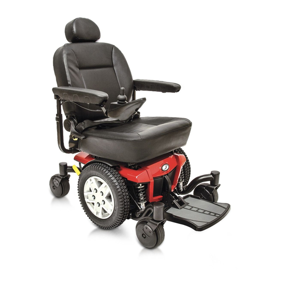
- Page 1 Parts Replacement Guide (Image is for illustration purposes only.) Pride Mobility Products Ltd. 32 Wedgwood Road Bicester, Oxfordshire OX26 4UL Telephone: (+44) 1869 324600 Fax: (+44) 1869 323070 Web: www.pridemobility.co.uk...
- Page 2 Introduction and Warnings Mobility Products. Ltd. Your new Quantum Rehab Parts Replacement Guide has been compiled from the latest product information available at the time of publication. Pride ® Mobility Products Ltd. reserves the right to make changes and updates to this manual and to the product(s) it represents.
-
Page 3: Table Of Contents
Table of Contents Mobility Products. Ltd. SECTION I. Foot Platform/Front Battery Door and Rear Electronics Door ..................6 SECTION II. Centre Panel and Top Shroud ............................7 SECTION III. Run Flat Drive Wheel ..............................8 SECTION IV. Front/Rear Castor Assembly ............................9 SECTION V. Articulating Beam................................10 SECTION VI. - Page 4 Chair Preparations Mobility Products. Ltd. All of the replacement instructions require safety precautions prior to performing service to the mobility device. These precautions are set in place not only to ensure the safety of the technician but for the end user as well. The replace- ment instructions in the guide will refer back to this section to set-up the product prior to service.
- Page 5 Seating Removal Mobility Products. Ltd. Several service applications require the removal of the seat. The illustration below outlines the connection points of the seating system to the power base. Torque the screws to To Seat Base Euro Seat 2 Interface removal and installation Torque the screws to Seat removal and installation www.pridemobility.co.uk...
-
Page 6: Foot Platform/Front Battery Door And Rear Electronics Door
I. Foot Platform/Front Battery Door and Rear Electronics Door Mobility Products. Ltd. 1. Turn off power to the joystick. 2. Ensure the unit is in drive mode. Tools Required: - None - Front Battery Door Removal/Installation: 3. Flip up the foot platform (if applicable), squeeze the release levers and lift the front battery door off of the frame. 4. -
Page 7: Centre Panel And Top Shroud
II. Centre Panel and Top Shroud Mobility Products. Ltd. 1. Turn off power to the joystick. 2. Ensure the unit is in drive mode. Tools Required: - Phillips Screwdriver - Centre Panel Removal/Installation: 3. Remove the rear electronics door. See Section I. 4. -
Page 8: Run Flat Drive Wheel
III. Run Flat Drive Wheel Mobility Products. Ltd. 1. Turn off power to the joystick. 2. Ensure the unit is in drive mode. 3. Prop up the side of the unit being serviced. Tools Required: - Imperial and Metric Socket Set - Calibrated Torque Spanner/Wrench - 5 Spoke Hub Run Flat Drive Wheel Removal/Installation: 4. -
Page 9: Front/Rear Castor Assembly
IV. Front/Rear Castor Assembly Mobility Products. Ltd. 1. Turn off power to the joystick. 2. Ensure the unit is in drive mode. 3. Prop up the side of the unit being serviced. Tools Required: - Imperial and Metric Socket Set - Imperial and Metric Spanner Set - Calibrated Torque Spanner/Wrench - Flathead Screwdriver... -
Page 10: Articulating Beam
V. Articulating Beam Mobility Products. Ltd. 1. Turn off power to the joystick. 2. Ensure the unit is in drive mode. 3. Prop up the rear of the unit. Tools Required: - Metric Socket Set - Metric Spanner Set - Calibrated Torque Spanner/Wrench - Flathead Screwdriver 4. -
Page 11: Drive Motor
VI. Drive Motor Mobility Products. Ltd. 1. Turn off power to the joystick. 2. Ensure the unit is in drive mode. 3. Prop up the side of the unit being serviced. Tools Required: - Imperial and Metric Socket Set - Calibrated Torque Spanner/Wrench - Imperial and Metric Hex Key Set - Phillips Screwdriver Axle Key... - Page 12 VI. Drive Motor Mobility Products. Ltd. 9. Disconnect the desired motor harness from the power module. 10. Carefully cut the cableties that may secure the motor harness to the main battery harness. 11. Remove the 6 screws that connect the motor assembly to the motor bracket.
-
Page 13: Foot Platform
VII. Foot Platform Mobility Products. Ltd. 1. Turn off power to the joystick. 2. Ensure the unit is in drive mode. Tools Required: - Metric Socket Set - Metric Spanner Set 3. To ease service, remove the front battery door with the foot platform attached. See Section I. 4. -
Page 14: Batteries
VIII. Batteries Mobility Products. Ltd. 1. Turn off power to the joystick. 2. Ensure the unit is in drive mode. Tools Required: - Metric Socket Set - Metric Spanner Set 3. Remove the front battery door. See Section I. 4. Disconnect the quick disconnect harnesses and remove the batteries. 5. -
Page 15: Joystick
IX. Joystick Mobility Products. Ltd. 1. Turn off power to the joystick. 2. Ensure the unit is in drive mode. Tools Required: - Phillips Screwdriver - Wire Cutters 3. Disconnect the joystick harness from the bus extension cable that is located near the back of the unit. Cableties may need to be cut to free the joystick cable. -
Page 16: Power Module
X. Power Module Mobility Products. Ltd. 1. Turn off power to the joystick. 2. Ensure the unit is in drive mode. Tools Required: - Phillips Screwdriver 3. Remove the rear electronics door. See Section I. 4. Remove the 2 screws that secure the power module to the frame. -
Page 17: Battery/Power Harness And Circuit Breaker
XI. Battery/Power Harness and Circuit Breaker Mobility Products. Ltd. 1. Turn off power to the joystick. 2. Ensure the unit is in drive mode. 3. Disconnect the joystick and all harnesses that connect to the power base. R-Net PLPM or VR2 Tools Required: - Phillips Screwdriver - Wire Cutters... - Page 18 (Image is for illustration purposes only.) Pride Mobility Products Ltd. 32 Wedgwood Road Bicester, Oxfordshire OX26 4UL Telephone: (+44) 1869 324600 Fax: (+44) 1869 323070 Web: www.pridemobility.co.uk...
Need help?
Do you have a question about the Quantum Rehab J600ES and is the answer not in the manual?
Questions and answers