Pride Mobility Jet 7 Owner's Manual
Power chair
Hide thumbs
Also See for Jet 7:
- Troubleshooting manual (3 pages) ,
- Owner's manual (44 pages) ,
- Owner's manual (43 pages)
Table of Contents

Related Manuals for Pride Mobility Jet 7


Summary of Contents for Pride Mobility Jet 7
- Page 1 Owner’s Manual ATTENTION: Please read the content of your owner’s manual before operating your power chair. Stylish Design and Premium Performance ® 21 Healey Road Dandenong, 3175 Victoria, Australia ACN# 088 609 661 www.pridemobility.com...
- Page 2 Copyright ©2002 Pride Mobility Products Corp. INFMANU1915/REV A/OCTOBER 2002...
-
Page 3: Table Of Contents
Table of Contents ............................4 NTRODUCTION ..........................4 OWER HAIR ..........................4 ESCRIPTION ..........................6 PECIFICATIONS .............................. 7 PERATION ..............7 OW TO RANSFER NTO AND FF OF OWER HAIR ......................7 ISSING OR AMAGED ARTS ........................7 AFETY RECAUTIONS ..................... -
Page 4: Introduction
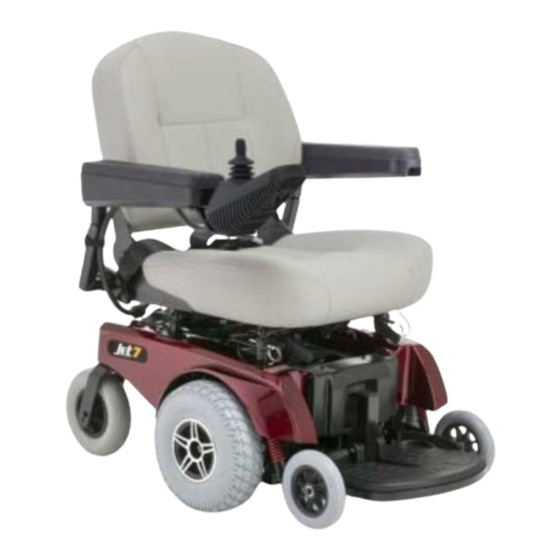
DESCRIPTION Your Pride Jet 7 is a motorised, mid-wheel drive power chair that is designed to operate both indoors and outdoors (in clear weather). It is sufficiently compact and maneuverable for some indoor environments but is also capable of negotiating some outdoor obstacles as well. - Page 5 Figure 1. The Jet 7 MOTOR CONNECTORS SEAT POSTS ONBOARD BATTERY CHARGER (LOCATED UNDER ELECTRONICS TRAY) REAR BATTERY MANUAL BATTERY FREEWHEEL CONNECTORS LEVERS FRONT BATTERY BOX BATTERY CONNECTION LABEL SEAT POSTS Figure 2. Jet 7 Power Base JET7/REV A/OCTOBER 2002 WWW.PRIDEMOBILITY.COM...
-
Page 6: Specifications
JET 7 SPECIFICATIONS Class of Use: Maximum Safe Slope: 8.7% Maximum Climbing Ability: 8.7% Maximum Obstacle Climbing Ability: 5 cm Drive Wheels: 25 cm, solid, centre-mounted (pneumatic tyres are optional) Brakes: Electronic regenerative, "Intelligent Braking" Caster Wheels: 20 cm, solid tyres... -
Page 7: Operation
Operation Your power chair is designed to provide optimum stability under normal driving conditions such as dry, level surfaces com- posed of concrete, blacktop, or asphalt. However, Pride recognises that there may be times when you will encounter other types of surfaces. For this reason, your power chair can also drive on packed soil, grass, and gravel. Feel free to use your power chair safely on dry lawns and in park areas as well. -
Page 8: Maximum Recommended Slope
WARNING! Your power chair's performance may be influenced by electromagnetic fields caused by mobile telephones or other radiating devices, such as hand-held radios, radio and television stations, wireless com- puter links, microwave sources, and paging transmitters. WARNING! Your power chair can be a source of electromagnetic and radio frequency interference. MAXIMUM RECOMMENDED SLOPE Pride performs extensive testing on our power chairs. -
Page 9: Electrical System
MAIN CIRCUIT BREAKER The main circuit breaker is a safety feature built into your Jet 7. It is located on the back battery box. See figure 4. When the batteries and the motors are heavily strained (e.g., from excessive loads), the main circuit breaker will trip to prevent damage to the motors and the electronics. -
Page 10: Battery Replacement
3. Plug the charger lead into the receptacle on the connector housing. 4. Extend the charger power lead and plug it into the wall outlet. The Jet 7 incorporates an inhibit function that disables the power chair when the charger is plugged into a wall outlet. -
Page 11: Frequently Asked Questions
15. Place the front battery box back into the Jet battery well. 16. Connect the rear battery box connector and the front battery box connector to the electronics tray. 17. Reassemble the Jet 7. See “Assembly.” NOTE: It is important to be sure that your battery connections are tight and secure. -
Page 12: Motor/Brake Assembly
MANUAL FREEWHEEL LEVERS For convenience, your Jet 7 is equipped with two manual freewheel levers located on the front of your Jet 7. See figures 5 and 6. These levers allow you to disengage the drive motors and maneuver the chair manually. -
Page 13: Seating System
Figure 9. Motor/Brake Assembly Seating System After you have used your Jet 7 for an extended period of time, you may find the need to make some adjustments to increase your comfort. WARNING! If your Jet 7 was configured by your authorised Pride provider, please consult them before making any adjustments. -
Page 14: Armrest Width And Height
2. Remove the battery boxes. REMOVE BALL DETENT PIN TO CHANGE SEAT HEIGHT. 3. Remove the ball detent pin from each seat post. See figure 10. 4. Raise or lower each seat tower to the desired position. 5. Install the ball detent pin into each seat post. 6. -
Page 15: Footrest Angle
6. Place the joystick mounting bracket in the other armrest. 7. Tighten the setscrew in each armrest. CONTROLLER MOUNTING 8. Connect the controller cable to the armrest with a new BRACKET tie-wrap. See figure 14. FOOTREST ANGLE LOOSEN THIS SETSCREW You can adjust the angle of the footrest with a 5-mm hex span- TO ADJUST THE CONTROLLER. -
Page 16: Wheels And Suspension
TYRE REPLACEMENT Your Jet 7 is equipped with solid tyres. Periodically check the tyres for excessive wear. If your tyre requires replacement, you must replace the entire wheel assembly. Replacement wheel assemblies are readily available at your authorised Pride pro- vider. -
Page 17: Disassembly
“snap” together or “snap” apart. NOTE: During both the disassembly and the assembly of the Jet 7, you may find it helpful to engage the Jet drive motors so that it does not roll while you are disassembling or assembling it. See “Motor/Brake Assembly.”... - Page 18 SEAT RELEASE PLUNGERS WARNING! Do not pick up the seat frame by the armrests. They are free to pivot, and you may lose control of the seat if they do so, resulting in personal injury and/or damage to the chair. Remove the footrest.
-
Page 19: Assembly
Assemble the front frame and power base frame assemblies. Assembly 1. Place the three frame assemblies next to each other as shown in figure 22. 2. Grasp the front frame and fit the bottom bar notch onto the locat- ing pin on the lower section of the power base frame assembly. See figure 23. -
Page 20: Vsi Controller
VSI Controller The electronic controller is what you use to operate your power chair. It takes the battery voltage and sends it to the appropriate system. The electronic con- troller enables you to move the power chair, as well as monitor battery charge, electronic controller func- tions, and the condition of your electrical system. - Page 21 Red lights only lit or slow flash: Charge battery as soon as pos- sible; VSI and electrical system OK. Rapid flash of lights: Indicates a fault in the VSI or the electrical system. Refer to “VSI Error Codes.” Ripple up and down of lights: The joystick was not in the neutral position when the controller was turned on.
- Page 22 THERMAL ROLLBACK The VSI controller is equipped with a thermal rollback circuit. The circuit monitors the temperature of the controller, which roughly translates to motor temperature. In the event that the VSI controller becomes excessively hot (above 140° F), motor current (amperage) is reduced.
-
Page 23: Pilot Controller
Pilot Controller BATTERY CONDITION METER ON/OFF BUTTON Your power chair may be equipped with a Pilot controller. The joystick is housed in the same enclosure as the controller. This assembly is mounted on the seat JOYSTICK arm. The Pilot controller is connected to the motors and the batteries through the controller connector and the charger harness connector. -
Page 24: Care And Maintenance
Care and Maintenance PREVENTIVE MAINTENANCE Refer to the table below for a recommended maintenance schedule. If, after you perform the following periodic maintenance checks, you perceive that there is a problem with your power chair, contact your authorised Pride provider. i t s l l o l l o... -
Page 25: How To Prepare Your Power Chair For Storage
CAUTION! Some of the parts of your Jet 7 are susceptible to extreme changes in temperature. Always keep your Jet 7 between the temperatures of -8°C/18°F and 50°C/122°F. -
Page 26: Warranty
Warranty FIVE-YEAR LIMITED WARRANTY Structural frame components, including platform, fork, seat posts, and frame welds. TWO-YEAR WARRANTY Drivetrain, including differential, motor, and brakes. ONE-YEAR WARRANTY Your Pride Power Chair is fully guaranteed for twelve (12) months from the date of purchase against faults arising due to defects in manufacture or materials.
Need help?
Do you have a question about the Jet 7 and is the answer not in the manual?
Questions and answers