Table of Contents
Advertisement
Quick Links
Advertisement
Table of Contents

Related Manuals for Milesight Pro Series


Summary of Contents for Milesight Pro Series
- Page 1 Industrial Router Pro Series UR35 Quick Start Guide...
- Page 2 Safety Precautions Milesight will not shoulder responsibility for any loss or damage resulting from not following the instructions of this operating guide. The device must not be modified in any way. Do not place the device close to objects with naked flames.
- Page 3 Revision History Date Doc Version Description Aug. 1, 2019 V 1.0 Initial version 1. Replace serial port picture; Feb. 11, 2020 V 1.1 2. Delete reboot descriptions of reset button 1. Web GUI change; Aug. 26, 2020 V 1.2 2. 2.Add -485 model Nov.
-
Page 4: Table Of Contents
Contents 1. Packing List................................5 2. Hardware Introduction............................6 2.1 Overview................................6 2.2 Dimensions..............................6 2.3 Serial & IO & Power Pinouts......................... 7 2.4 LED Indicators..............................7 2.5 Reset Button..............................8 2.6 Ethernet Port Indicator..........................8 3. Hardware Installation.............................. 9 3.1 SIM Card/Micro SD Card Installation......................9 3.2 Antenna Installation............................ -
Page 5: Packing List
1. Packing List Before you begin to install the UR35 router, please check the package contents to verify that you have received the items below. 2 × Magnetic Cellular 1 × UR35 1 × Ethernet Cable 1 × Power Adapter Antennas 1 ×... -
Page 6: Hardware Introduction
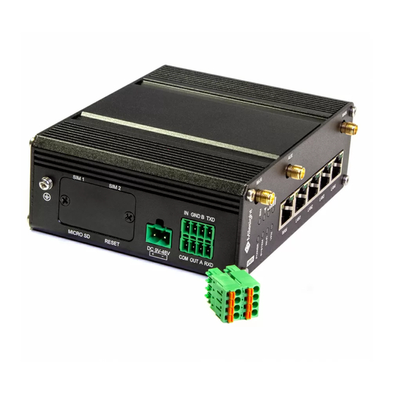
2. Hardware Introduction 2.1 Overview A. Front Panel Wi-Fi Antenna Connector AUX Antenna Cellular Connector GPS Antenna Connector MAIN Cellular Antenna Connector LED Indicator Area POWER: Power Indicator SYSTEM: Status Indicator Wi-Fi: Wi-Fi Indicator VPN: VPN Indicator SIM : SIM Status Indicator : Signal Strength Indicator Ethernet Port &... -
Page 7: Serial & Io & Power Pinouts
2.3 Serial & IO & Power Pinouts RS232 RS485 Description Digital Input Ground Data - Transmit Data Common Ground Digital Output Data + Receive Data Note: For -RS485 model, RXD--->A, TXD--->B. Description Wire Color Positive Negative Black 2.4 LED Indicators Indication Status Description... -
Page 8: Reset Button
registered and is dialing up now Static: SIM2 (as primary SIM) has been registered and dialed up successfully No signal Static/Off/Off: weak signals with 1-10 ASU (please check if the antenna is installed correctly, or move the Signal antenna to a suitable location to get better signal) Signal 1/2/3 Strength Green Light... -
Page 9: Hardware Installation
3. Hardware Installation Environmental Requirements - Power Input: 9-48 VDC (48 VDC is needed for PoE output) - Power Consumption: Typical 3.9 W (Max 4.6 W) - Operating Temperature: -40°C to 70°C (-40°F -158°F) - Relative Humidity: 0% to 95% (non-condensing) at 25°C/77°F 3.1 SIM Card/Micro SD Card Installation UR35 do not support hot-plug. -
Page 10: Din Rail Mounting
3.3.1 DIN Rail Mounting (Measured in mm) Use 2 pcs of M3 × 6 flat head Phillips screws to fix the mount clip to the router, and then hang the device to the DIN rail. The width of DIN rail is 3.5cm. Recommended torque for mounting is 1.0 N·m, and the maximum allowed is 1.2 N·m. -
Page 11: Log In The Web Gui Of Router
4. Log in the Web GUI of Router Please connect PC to LAN port of UR35 router. PC can obtain an IP address, or you can configure a static IP address manually. The following steps are based on Windows 10 operating system for your reference. - Page 12 D. Enter the username, password, and click "Login". If you enter the username or password incorrectly more than 5 times, the login page will be locked for 10 minutes. E. When you login with the default username and password, you will be asked to modify the password. It’s suggested that you change the password for the sake of security.
-
Page 13: Network Configuration
5. Network Configuration This chapter explains how to connect UR35 to network via WAN connection or cellular. 5.1 Ethernet WAN Configuration A. Go to “Network > Interface > WAN” to select connection type and configure WAN parameters, click “Save & Apply” button to make the changes take effect. B. - Page 14 info, click “Save” and “Apply” to save the configuration. B. Go to “Network > Interface > Link Failover” to enable SIM1 and rise link priority of SIM1. C. Click to configure ICMP ping detection information.
- Page 15 D. Click “Status > Cellular” to view the status of the cellular connection. If it shows “Connected”, it means SIM1 has dialed up successfully. On the other hand, you can check the status of SIM indicator. If it keeps on green light statically, it means SIM1 has dialed up successfully. E.
Need help?
Do you have a question about the Pro Series and is the answer not in the manual?
Questions and answers