
Related Manuals for Clarke MIG85ENB


Summary of Contents for Clarke MIG85ENB
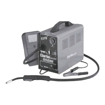
- Page 1 NO GAS MIG WELDER NO GAS MIG WELDER MIG85ENB Part No. 6010109 0606 OPERATING & MAINTENANCE INSTRUCTIONS...
-
Page 2: Guarantee
CLARKE GUARANTEE This CLARKE product is guaranteed against faulty manufacture for a period of 12 months from the date of purchase. Please keep your receipt as proof of purchase. -
Page 3: Table Of Contents
CONTENTS PAGE Guarantee ....................2 Electromagnetic Interference (EMC) ..........4 Safety Precautions ................. 6 Additional Safety Precautions for MIG Welding ....... 11 Principles of Operation ................ 13 Electrical Connections ................ 14 Unpacking and Parts Identification ........... 15 Assembly ....... Installing Welding Wire ......16 Welding Shield ........... -
Page 4: Electromagnetic Interference (Emc)
ELECTROMAGNETIC INTERFERENCE (EMC) Whilst this unit complies with EMC regulations, the user is responsible for installing and using the welding equipment according to the manufacturers instructions. If electromagnetic disturbances are detected then it shall be the responsibility of the user of the welding equipment to resolve the situation. In some cases this remedial action may be as simple as earthing the welding circuit, see ‘Note’. - Page 5 take additional precautions such as filtering of the mains supply. Consideration should be given to shielding the supply cable of permanently installed welding equipment, in metallic conduit or equivalent. Shielding should be electrically continuous throughout its length. The shielding should be connected to the welding power source so that good electrical contact is maintained between the conduit and the welding power source enclosure.
-
Page 6: Safety Precautions
SAFETY PRECAUTIONS FOR ALL TYPES OF WELDING 1. WARNING: As with all machinery, there are certain hazards involved with their operation and use. Exercising respect and caution will considerably lessen the risk of personal injury. However, if normal safety precautions are overlooked, or ignored, personal injury to the operator may result. - Page 7 C) Fire and explosion prevention Causes of fire and explosion are: 1) combustibles reached by the arc, flame, flying sparks, hot slag or heated material; 2) misuse of compressed gases and cylinders; 3) short circuits. BE AWARE THAT flying sparks or falling slag can pass through cracks, along pipes, through windows or doors, and through wall or floor openings, out of sight of the goggled operator.
- Page 8 3. ELECTRIC ARC (MIG, TIG) WELDING Comply with precautions in 1 above, and this section. Arc welding, properly done, is a safe process, but a careless operator invites trouble. The equipment carries high currents at significant voltages. The arc is very bright and hot. Sparks fly, fumes rise, ultraviolet and infrared energy radiates, weldments are hot.
- Page 9 3B) TOXIC FUME PREVENTION Comply with precautions in 2B. Generator engine exhaust must be vented to the outside air. Carbon monoxide can kill. 3C) FIRE AND EXPLOSION PREVENTION Comply with precautions in 2C. Equipment’s rated capacity. Do not overload arc welding equipment.
- Page 10 2) Electrode holders Fully insulated electrode holders should be used. Do NOT use holders with protruding screws or with any form of damage. 3) Connectors Fully insulated lock-type connectors should be used to join welding cable. 4) Cables Frequently inspect cables for wear, cracks and damage. IMMEDIATELY REPLACE those with excessively worn or damaged insulation to avoid possibly lethal shock from bared cable.
-
Page 11: Additional Safety Precautions For Mig Welding
NEVER remove any of the panels unless the machine is disconnected from the supply, AND never use the machine with any of the panels removed. NEVER attempt any electrical or mechanical repair unless your are a qualified technician. If you have a problem with the machine contact your local CLARKE dealer. - Page 12 NEVER use or store in a wet/damp environment. DO NOT EXPOSE TO RAIN. NEVER continue to weld, if, at any time, you feel even the smallest electric shock. Stop welding IMMEDIATELY, and DO NOT attempt to use the machine until the fault is diagnosed and corrected.
-
Page 13: Principles Of Operation
SAFETY EQUIPMENT A comprehensive range of CLARKE safety equipment for use when welding is available from your local dealer. NO-GAS WELDING - PRINCIPLES OF OPERATION MIG (Metal Inert Gas) welding is a process in which a power wire electrode is fed continuously into the weld pool at a controlled, constant rate. -
Page 14: Electrical Connections
ELECTRICAL CONNECTIONS WARNING! THIS APPLIANCE MUST BE EARTHED. The welder is fitted with a standard 13 amp BS 1363 plug, fitted with a 13 amp fuse. Connect to a 230 volt (50Hz) domestic electrical supply and we strongly recommend that this be done via a Residual Current Device (RCD). IMPORTANT: The wires in the mains lead are coloured in accordance with the following code: Green &... -
Page 15: Unpacking And Parts Identification
UNPACKING & PARTS IDENTIFICATION Unpack and lay out the components, checking against the following list. Any damage or deficiency should be reported to your CLARKE dealer immediately. Some of the components are stored within Fig.1 the side compartment. To open the compartment, pull the side panel up, as indicated in Fig.1. -
Page 16: Assembly
ASSEMBLY & INSTALLATION A. INSTALLING THE WELDING WIRE NOTE: This machine is supplied with a Clarke ‘Mini’ spool of 0.9mm, mild steel, flux cored welding wire. Replaceable spools available from your Clarke dealer. See ‘Accessories’ for full details. IMPORTANT: Ensure that the electrical supply is disconnected. - Page 17 Re: Fig.5 Fig.5 Pull out the end of the wire from the rim of the spool, taking care NOT to release it. The spool is wound firmly and should remain this way. Ensuring the wire is straight and not kinked in any way, clip off the end cleanly, ensuring there are no burrs or sharp edges.
-
Page 18: Welding Shield
It is important to pay attention to the notes on welding shield maintenance, given on page 22. When replacing the glass panels, use ONLY those parts supplied by Clarke International. The dark panel is a certified, specific optical class, and should not be exchanged for any other type. -
Page 19: Preparation For Use Preparing The Work
PREPARATION FOR USE A. PREPARE THE WORK MOST IMPORTANT! It is VITAL that the workpiece is perfectly clean at the point of weld. Any coating, plating or corrosion MUST be removed, otherwise a good weld will be impossible to achieve. B. -
Page 20: Attaching The Earth Clamp
Workpiece Thickness Current Setting Wire Feed (mm) 0 - 2.0 2.0 - 4.0 The 10-position wire speed control should be set to 6 to begin with, then adjusted as required. (See notes under ‘Operation). D. Trim the Welding Wire Trim the welding wire so that it protrudes no more than 5mm from the end of the contact tip. -
Page 21: Mig Welding Operation
OPERATION Plug the machine into the mains supply or switch on at the isolator, and, ensuring all precautions have been taken and with the machine set up correctly, lower the torch to the workpiece with one hand, whilst holding the welding mask in the other. -
Page 22: Welding Tips
Replacement clear and dark lenses are available from your Clarke dealer - see Parts Lists for details. NEVER use any dark filter lens other than that provided by CLARKE International, or one with the same certified ‘Optical class’... -
Page 23: Troubleshooting
TROUBLESHOOTING Your Clarke Mig Welder has been designed to give long and trouble free service. If, however, having followed the instructions in this booklet carefully, you still encounter problems, the following points should help identify and resolve them. PROBLEM CAUSE REMEDY 1. -
Page 24: Parts Lists
PARTS DIAGRAM... - Page 25 PARTS LIST Description Part No. Input Cable EN20220068 Handle EN21600030 Plastic Wire Feeder EN44400018 Wire Feed Roll EN33805074 Side Panel EN33705482 Torch Grommet EN21690458 Welding Current Switch EN22200006 Potentiometer Knob EN21690309 Yellow Pilot-light Switch EN22200022 Right Upper Panel EN33705324 Motor Control PC Board EN22710047 Dividing Panel EN33720159...
-
Page 26: Wiring Diagrams
WIRING DIAGRAM PARTS & SERVICE CONTACTS For Spare Parts and Service, please contact your nearest dealer, or CLARKE International, on one of the following numbers. PARTS & SERVICE TEL: 020 8988 7400 PARTS & SERVICE FAX: 020 8558 3622 e-mail as follows: PARTS: Parts@clarkeinternational.com... -
Page 27: Welder Specifications
Part No................6010109 Please note that the details and specifications contained herein, are correct at the time of going to print. However, CLARKE International reserve the right to change specifications at any time without prior notice. ALWAYS CONSULT THE MACHINE’S DATA PLATE * Duty Cycle: Determines the machine ‘down time’.
Need help?
Do you have a question about the MIG85ENB and is the answer not in the manual?
Questions and answers