
Related Manuals for Clarke MIG PRO-90


Summary of Contents for Clarke MIG PRO-90
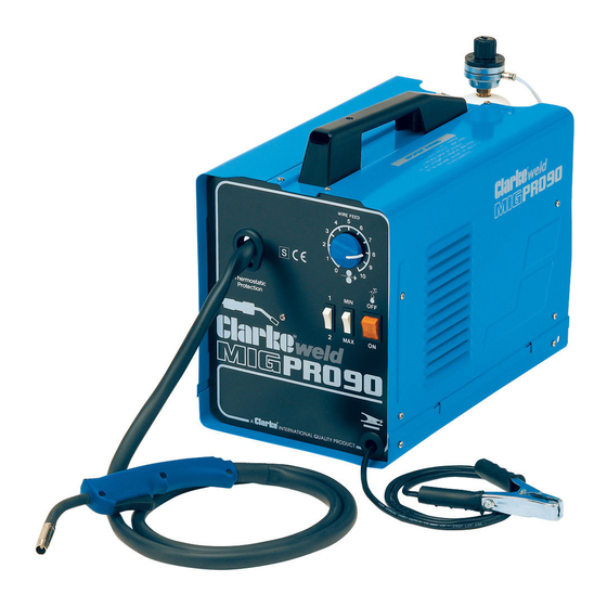
- Page 1 MIG PRO-90 • MIG 100E • MIG 150TE MIG PRO-90 • MIG 100E • MIG 150TE 0904 OPERATING & MAINTENANCE INSTRUCTIONS...
-
Page 2: Table Of Contents
CONTENTS PAGE Guarantee ....................3 Parts & Service Contacts ............... 3 Electromagnetic Interference (EMC) ..........4 Safety Precautions ................. 6 Additional Safety Precautions for MIG Welding ....... 11 Principles of Operation ................ 13 Electrical Connections ................ 14 Unpacking and Parts Identification ........... 15 Assembly ....... -
Page 3: Guarantee
GUARANTEE This CLARKE product is guaranteed against faulty manufacture for a period of 12 months from the date of purchase. Please keep your receipt as proof of purchase. This guarantee is invalid if the product is found to have been abused or tampered with in any way, or not used for the purpose for which it was intended. -
Page 4: Electromagnetic Interference (Emc)
ELECTROMAGNETIC INTERFERENCE (EMC) Whilst this unit complies with EMC regulations, the user is responsible for installing and using the welding equipment according to the manufacturers instructions. If electromagnetic disturbances are detected then it shall be the responsibility of the user of the welding equipment to resolve the situation. In some cases this remedial action may be as simple as earthing the welding circuit, see ‘Note’. - Page 5 take additional precautions such as filtering of the mains supply. Consideration should be given to shielding the supply cable of permanently installed welding equipment, in metallic conduit or equivalent. Shielding should be electrically continuous throughout its length. The shielding should be connected to the welding power source so that good electrical contact is maintained between the conduit and the welding power source enclosure.
-
Page 6: Safety Precautions
SAFETY PRECAUTIONS FOR ALL TYPES OF WELDING 1. WARNING: As with all machinery, there are certain hazards involved with their operation and use. Exercising respect and caution will considerably lessen the risk of personal injury. However, if normal safety precautions are overlooked, or ignored, personal injury to the operator may result. - Page 7 C) Fire and explosion prevention Causes of fire and explosion are: 1) combustibles reached by the arc, flame, flying sparks, hot slag or heated material; 2) misuse of compressed gases and cylinders; 3) short circuits. BE AWARE THAT flying sparks or falling slag can pass through cracks, along pipes, through windows or doors, and through wall or floor openings, out of sight of the goggled operator.
- Page 8 3. ELECTRIC ARC (MIG, TIG) WELDING Comply with precautions in 1 above, and this section. Arc welding, properly done, is a safe process, but a careless operator invites trouble. The equipment carries high currents at significant voltages. The arc is very bright and hot. Sparks fly, fumes rise, ultraviolet and infrared energy radiates, weldments are hot.
- Page 9 3B) TOXIC FUME PREVENTION Comply with precautions in 2B. Generator engine exhaust must be vented to the outside air. Carbon monoxide can kill. 3C) FIRE AND EXPLOSION PREVENTION Comply with precautions in 2C. Equipment’s rated capacity. Do not overload arc welding equipment.
- Page 10 2) Electrode holders Fully insulated electrode holders should be used. Do NOT use holders with protruding screws or with any form of damage. 3) Connectors Fully insulated lock-type connectors should be used to join welding cable. 4) Cables Frequently inspect cables for wear, cracks and damage. IMMEDIATELY REPLACE those with excessively worn or damaged insulation to avoid possibly lethal shock from bared cable.
-
Page 11: Additional Safety Precautions For Mig Welding
NEVER attempt any electrical or mechanical repair unless your are a qualified technician. If you have a problem with the machine contact your local CLARKE dealer. ✗ NEVER use or store in a wet/damp environment. DO NOT EXPOSE TO RAIN. - Page 12 ✗ NEVER Use a damaged cylinder. Lift the cylinder by the valve. Expose the cylinder to a heat source or sparks. ✗ NEVER continue to weld, if, at any time, you feel even the smallest electric shock. Stop welding IMMEDIATELY, and DO NOT attempt to use the machine until the fault is diagnosed and corrected.
-
Page 13: Principles Of Operation
SAFETY EQUIPMENT A comprehensive range of CLARKE safety equipment for use when welding is available from your local dealer. MIG WELDING - PRINCIPLES OF OPERATION MIG (Metal Inert Gas) welding is a process in which a power wire electrode is fed continuously into the weld pool at a controlled, constant rate. -
Page 14: Electrical Connections
ELECTRICAL CONNECTIONS WARNING! THIS APPLIANCE MUST BE EARTHED. A. MIG’s PRO-90 and 100E ONLY These welders are fitted with a standard 13 amp BS 1363 plug, fitted with a 13 amp fuse. Connect to a 230 volt (50Hz) domestic electrical supply and we strongly recommend that this be done via a Residual Current Device (RCD). -
Page 15: Unpacking And Parts Identification
UNPACKING & PARTS IDENTIFICATION Unpack and lay out the components, checking against the following list. Any damage or deficiency should be reported to your CLARKE dealer immediately. Most of the components are stored within the side compartment. To open the compartment, slide the side cover upwards. -
Page 16: Assembly
B. Installing the Welding Wire NOTE: These machines are designed to accept either the Clarke ‘Mini’ or 5kg wire spools of mild steel, stainless steel or aluminium according to the type of metal you wish to weld. Mini Mild Steel wire spools are supplied with the machine..others must be purchased separately. - Page 17 Replace the collar, spring and plastic knob, tightening the knob sufficiently to allow the spool to rotate smoothly but with a slight amount of braking friction. Do not over tighten as this will exert undue pressure on the wire drive motor and may cause serious damage.
-
Page 18: Selecting The Drive Roller Groove
Fig.5 (Ref. Fig 5) Unscrew and remove the torch shroud by twisting it anti clockwise, then unscrew the contact tip. Should any wire protrude from the tip..pull it out completely and discard. Close the side panel of the machine, plug into a 230V, 50HZ outlet (or switch on isolator). -
Page 19: Connecting The Gas Supply
A mini gas bottle complete with gas regulator is provided. Should you prefer to use larger gas cylinders, the appropriate gas regulator and fittings need to be acquired. Your Clarke dealer will be happy to advise in this regard. Fig.7 Attach the mini gas bottle to the machine as described in ‘Assembly’... -
Page 20: Welding Shield
It is important to pay attention to the notes on welding shield maintenance, given on page 25. When replacing the glass panels, use ONLY those parts supplied by Clarke International. The dark panel is a certified, specific optical class, and should not be exchanged for any other type. -
Page 21: Preparation For Use
PREPARATION FOR USE A. PREPARE THE WORK MOST IMPORTANT! It is VITAL that the workpiece is perfectly clean at the point of weld. Any coating, plating or corrosion MUST be removed, otherwise a good weld will be impossible to achieve. B. - Page 22 1. MIG PRO-90 Two, 2-pole switches are marked 1- 2 and MAX - MIN respectively, Set these switches according to the charts on pages 27-29. 2. MIG 100E Three, 2-pole switches are used, marked A - 1, 1 - 2 and MAX - MIN.
-
Page 23: Welding Wire Preparation
D. Trim the Welding Wire Trim the welding wire so that it protrudes no more than 5mm from the end of the shroud. E. Attach the Earth Lead Attach the earth lead to the workpiece with the earth clamp, as close to the point of weld as possible, without it being intrusive. -
Page 24: Thermal Overload
Thermal Overload A thermal overload is a safety device which shuts off the welder when the duty cycle has been exceeded. This is to prevent damage to the machine caused by overheating. When this occurs, the ON/OFF switch will glow (amber). Allow the welder to cool, until the amber light extinguishes before resuming. -
Page 25: Maintenance
- see Parts Lists for details. NEVER use any dark filter lens other than that provided by CLARKE International, or one with the same certified ‘Optical class’ (degree of protection). The shield should always be cleaned with a clean soft cloth after use, ensuring the lenses are clean. -
Page 26: Renewing The Wire Liner
RENEWING THE WIRE LINER Fig.12 If the liner becomes damaged or kinked, it will be necessary to replace it. Before commencing work, ensure the electrical supplies disconnected. Open the side cover, and remove the welding wire from the hose and torch assembly. (Refer to ‘Installing Welding Wire’... -
Page 27: Control Settings Reference Tables
CONTROL SETTINGS - REFERENCE TABLES A. MIG PRO-90 STEEL 0.6 mm Gas Welding Wire 0.8 mm Gas Welding Wire Workpiece Welding Wire Speed Welding Wire Speed Thickness Position Position Adjustment Adjustment (mm) 0.6 - 0.8 0.8 - 1.0 1.0 - 2.0 2.0 - 3.0... - Page 28 CONTROL SETTINGS - REFERENCE TABLES B. MIG 100E STEEL 0.6 mm Gas Welding Wire 0.8 mm Gas Welding Wire Workpiece Wire Speed Wire Speed Welding Welding Thickness Adjustment Position Adjustment Position (mm) 0.5 - 0.6 0.6 - 0.8 2/3 MAX 0.8 - 1.0 1.0 - 1.2 1.2 - 2.0...
- Page 29 CONTROL SETTINGS - REFERENCE TABLES B. MIG 150TE STEEL 0.6 mm Gas Welding Wire 0.8 mm Gas Welding Wire Workpiece Welding Wire Speed Welding Wire Speed Thickness Position Adjustment Position Adjustment (mm) 0.5 - 0.6 0.6 - 0.8 0.8 - 1.0 1.0 - 1.2 1.2 - 2.0 2.0 - 3.0...
-
Page 30: Welder Specifications
6 minutes and must have a down time of 4 minutes. Please note that the details and specifications contained herein, are correct at the time of going to print. However, CLARKE International reserve the right to change specifications at any time without prior notice. ALWAYS CONSULT THE MACHINE’S DATA PLATE... -
Page 31: Wiring Diagrams
WIRING DIAGRAMS MIG 100E MIG 150TE... - Page 32 PARTS LIST 150TE No. Description Handle-extension Knob EN21600006 Handle-extention EN33725015 Handle EN21600003 EN21600003 Complete Motor EN04600143 EN04600146 Complete Thermostat EN04600113 EN04600126 Complete Fan EN04600055 Cable Clamp EN21605032 EN21605032 Front Panel EN33710034 EN33710190 Welding Current Switch EN22200006 EN22200006 Potentiometer Knob EN21690018 EN21690018 Right-upper Panel EN33705031...
- Page 33 PARTS DIAGRAM...
-
Page 34: Troubleshooting
TROUBLESHOOTING Your Clarke Mig Welder has been designed to give long and trouble free service. If, however, having followed the instructions in this booklet carefully, you still encounter problems, the following points should help identify and resolve them. PROBLEM CAUSE REMEDY 1. -
Page 35: Accessories
8132270 4. Gas Regulator 8132000 In addition to the above, your Clarke dealer can provide you with a wide range of welding accessories, safety equipment etc., to increase productivity where necessary and to simplify and assist in the welding process.
Need help?
Do you have a question about the MIG PRO-90 and is the answer not in the manual?
Questions and answers