
Subscribe to Our Youtube Channel
Related Manuals for Clarke MIG 240


Summary of Contents for Clarke MIG 240
- Page 1 WARNING: Read these instructions before using the machine The welder is supplied set up for no gas welding GAS/NO GAS MIG WELDER MODEL NO: MIG 240 PART NO: 6014200 OPERATION & MAINTENANCE INSTRUCTIONS LS1118 - ISS 1...
-
Page 2: Introduction
GUARANTEE This CLARKE product is guaranteed against faulty manufacture for a period of 12 months from the date of purchase. Please keep your receipt as proof of purchase. -
Page 3: Consumable
CONSUMABLE The following are some of the consumables available from your CLARKE dealer. Please quote the part numbers shown below: PART DESCRIPTION PART COMMENT NUMBER Welding Wire Flux cored mild steel (4.5kg) 6000666 Use for no gas welding Spools 0.9mm Mild steel - 0.6mm (5 kg) -
Page 4: Table Of Contents
CONTENTS INTRODUCTION ............... 2 GUARANTEE ..............2 ENVIRONMENTAL RECYCLING POLICY ......2 CONSUMABLE ..............3 CONTENTS ............... 4 GENERAL SAFETY INSTRUCTIONS ........5 ELECTRICAL CONNECTIONS .......... 8 OVERVIEW ............... 9 The Control panel ..............10 OPENING THE SIDE PANEL ..........11 UNPACKING .............. -
Page 5: General Safety Instructions
GENERAL SAFETY INSTRUCTIONS WARNING: WHEN USING ELECTRICAL TOOLS, BASIC SAFETY PRECAUTIONS SHOULD ALWAYS BE FOLLOWED TO REDUCE THE RISK OF FIRE, ELECTRIC SHOCK AND PERSONAL INJURY WARNING: READ ALL THESE INSTRUCTIONS BEFORE ATTEMPTING TO OPERATE THIS PRODUCT AND KEEP THESE INSTRUCTIONS IN A SAFE PLACE. ELECTRIC SHOCK the weld seam and when not in use is insulated for safety. - Page 6 substances likely to generate a • Do not weld in the vicinity of dangerous vapour. children or animals and ensure no one is looking before striking an • The welding arc can cause serious arc. burns. Avoid contact with skin. •...
- Page 7 If you have a when not in use and between problem with the machine contact operations. your local CLARKE dealer. • Take care that a build-up of gas is • NEVER use or store in a wet/damp not permitted to form in confined environment.
-
Page 8: Electrical Connections
ELECTRICAL CONNECTIONS A STANDARD 13AMP PLUG MUST NOT BE USED WITH THIS UNIT. WARNING: READ THESE ELECTRICAL SAFETY INSTRUCTIONS THOROUGHLY BEFORE CONNECTING THE PRODUCT TO THE MAINS SUPPLY. The unit must be connected to a 230V socket cabable of supplying 32 Amps, We recommend that you consult a qualified electrician and connect the mains lead, through a suitably fused isolator switch Before switching the product on, make sure that the voltage of your electricity... -
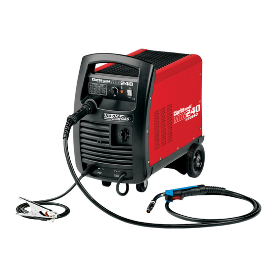
Page 9: Overview
OVERVIEW DESCRIPTION NO DESCRIPTION Handle Torch Gas Connection Point Torch Hose Control Panel Earth Clamp Parts & Service: 020 8988 7400 / E-mail: Parts@clarkeinternational.com or Service@clarkeinternational.com... -
Page 10: The Control Panel
THE CONTROL PANEL 1. Wire speed control knob. As a general rule, a higher current requires a higher wire speed. 2. Current setting dial. Provides 6 increasing power levels. Dial Setting Welding Current in Amps 100A 130A 180A 240A 3. Power ON/OFF switch. When the power is ON the green switch will be illuminated. -
Page 11: Opening The Side Panel
2. Remove loose items that have been transported inside. UNPACKING Any damage or deficiency should be reported to your CLARKE dealer immediately. Some of the components are stored within the machine side compartment. The components include the following: 1 x MIG TORCH Euro connection Torch (Quick release) 1 x 0.8mm tip for no gas welding in the torch... -
Page 12: Assembly
ASSEMBLY FITTING THE GAS BOTTLE BRACKET 1. Place the bottle bracket into position and secure in place using the screws provided. CONNECT THE TORCH Connect the plug on the end of the torch hose to the socket shown on the welder. CONNECT THE EARTH LEAD Insert the earth lead plug as shown. -
Page 13: The Welding Shield
CAUTION: WHEN REPLACING THE GLASS PANELS, ONLY USE PARTS SUPPLIED BY CLARKE INTERNATIONAL. THE DARK PANEL IS A CERTIFIED, SPECIFIC OPTICAL CLASS AND SHOULD NOT BE EXCHANGED FOR ANY OTHER TYPE. -
Page 14: Preparation For Use
MOUNTING THE WELDING WIRE SPOOL WARNING: MAKE SURE THAT THE WELDER IS NOT CONNECTED TO THE MAINS SUPPLY. NOTE: Spools of welding wire are available from your Clarke dealer. 1. Open the side panel by pushing the latch down and allowing the side panel to open. -
Page 15: Threading The Wire
5. Pull the roller off the drive spindle. • The groove size is stamped on the corresponding side of the roller. Select the groove size according to the size of the wire you are using and put the roller back on the spindle with your chosen side facing you. - Page 16 6. Close the side panel of the welder. 7. Pull off the torch shroud with a twisting movement, then unscrew the contact tip. 8. Connect the welder to the power supply and switch ON. 9. Set the ‘WIRE FEED’ rotary control on the front panel to position 7 or 8 and squeeze the trigger on the torch body.
-
Page 17: Mig Welding Principles
MIG WELDING PRINCIPLES MIG (Metal Inert Gas) welding allows you to fuse together two similar metals without altering the properties of the metal. A consumable wire electrode is continuously fed through the welding torch that is fitted with a concentric gas nozzle. the wire is connected to a high voltage supply which creates an electric arc between the electrode (the wire) and the workpiece. -
Page 18: Welding Without Gas
WELDING WITHOUT GAS 1. If you use 0.9mm flux cored wire, connect the terminal as shown. • The earth cable must be connected to the positive (upper) terminal. • The cable from torch must be connected to the Negative (lower) terminal. WELDING WITH GAS 1. -
Page 19: Operating The Welder
OPERATING THE WELDER PREPARE THE WORKPIECE The welded area must be clean. Coatings, plating or corrosion must be removed. If not, you will not be able to achieve a good quality weld. Attach the earth clamp to the workpiece as near to the point of weld as possible. -
Page 20: Thermal Overload
tuning, it should not be necessary to adjust this control when the welding current is changed. NOTE: Listen to the sound made. An irregular crackling sound denotes too high a wire speed. Decrease the speed until a regular, strong buzzing sound is heard. THERMAL OVERLOAD The ‘Thermal Overload’... -
Page 21: Maintenance
Check the hose for security and damage. As a general rule the power supply should be inspected at least annually. Consult your CLARKE dealer for advice if necessary. Wire feed unit: The feed roller wire guide plays an important part in obtaining consistent results. -
Page 22: Rating Plate
RATING PLATE Name and address of manufacturer Load Voltage symbol Model number, part number Energy Input symbol Batch number Rated supply voltage Single phase transformer-rectifier Rated maximum supply current British Standards applied Maximum effective supply current Welding process This symbol indicates that the unit is suitable for carrying out welding operations in an environment which has an increased risk of electric... -
Page 23: Specifications
1-8 mm The details and specifications contained herein, are correct at the time of going to print. However, CLARKE International reserve the right to change specifications at any time without prior notice. Parts & Service: 020 8988 7400 / E-mail: Parts@clarkeinternational.com or Service@clarkeinternational.com... -
Page 24: Arc Activated Headshields
ARC ACTIVATED HEADSHIELDS These highly popular headshields available from your Clarke dealer activate the instant the arc is struck and allow you to have both hands free when welding. Model Grinding Solar Fixed Flip Up Part Number Activated function Powered Shade ✔... -
Page 25: Troubleshooting
TROUBLESHOOTING Your CLARKE MIG Welder has been designed to give long and trouble free service. If, however, having followed the instructions in this booklet carefully, you still encounter problems, the following points should help identify and resolve them. PROBLEM CAUSE... - Page 26 If you have any problems which cannot be resolved by reference to the above, or if you require spare parts for your welder please contact your local Clarke dealer. Parts & Service: 020 8988 7400 / E-mail: Parts@clarkeinternational.com or Service@clarkeinternational.com...
-
Page 27: Declaration Of Conformity
DECLARATION OF CONFORMITY Parts & Service: 020 8988 7400 / E-mail: Parts@clarkeinternational.com or Service@clarkeinternational.com...
Need help?
Do you have a question about the MIG 240 and is the answer not in the manual?
Questions and answers