
Subscribe to Our Youtube Channel
Related Manuals for Clarke weld MIG107


Summary of Contents for Clarke weld MIG107
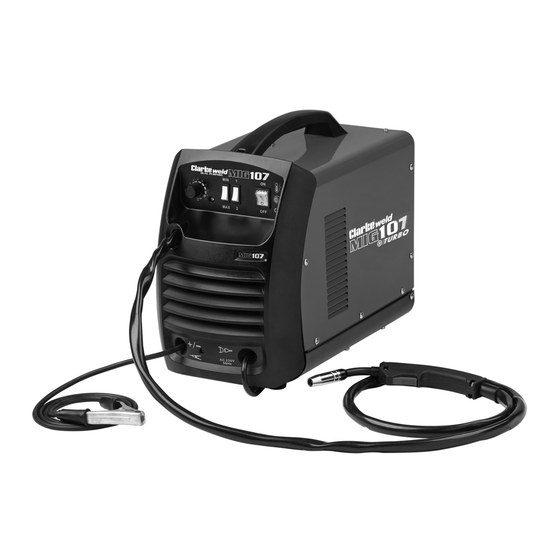
- Page 1 NO GAS/GAS MIG WELDER MODEL NO: MIG107 PART NO: 6014012 OPERATION & MAINTENANCE INSTRUCTIONS ORIGINAL INSTRUCTIONS GC03/24...
-
Page 2: Machine Specifications
Steel;- MIG 0.8 - 4mm Others;-MIG 0.8 - 4mm Earth cable length 1600mm Torch cable length 1800mm CLARKE International reserve the right to change specifications at any time without prior notice Parts & Service: 020 8988 7400 / E-mail: Parts@clarkeinternational.com or Service@clarkeinternational.com... -
Page 3: General Precautions
SAFETY PRECAUTIONS FOR ALL TYPES OF WELDING WARNING: AS WITH ALL MACHINERY, THERE ARE CERTAIN HAZARDS INVOLVED WITH THEIR OPERATION AND USE. EXERCISING RESPECT AND CAUTION WILL CONSIDERABLY LESSEN THE RISK OF PERSONAL INJURY. HOWEVER, IF NORMAL SAFETY PRECAUTIONS ARE OVERLOOKED, OR IGNORED, PERSONAL INJURY TO THE OPERATOR MAY RESULT. - Page 4 perchloroethylene vapours to form phosgene. DO NOT WELD or cut where solvent vapours can be drawn into the welding or cutting atmosphere or where the radiant energy can penetrate to atmospheres containing even minute amounts of trichloroethylene or perchloroethylene. C) FIRE AND EXPLOSION PREVENTION Causes of fire and explosion are: •...
- Page 5 A container with unknown contents should be cleaned (see paragraph above). Do NOT depend on sense of smell or sight to determine if it is safe to weld or cut. Hollow castings or containers must be vented before welding or cutting as they can explode.
-
Page 6: Fire And Explosion Prevention
may leave a permanent dark area in the field of vision. Before welding whilst wearing contact lenses, seek advice from your optician. PROTECTION OF NEARBY PERSONNEL For production welding, a separate, well vented room or enclosed bay is best. In open areas, surround the operation with low reflective, non- combustible screens or panels. - Page 7 power source, control, work table and water circulator to the building earth. Conductors must be adequate to carry earth currents safely. Equipment made electrically LIVE by stray current may shock, possibly fatally. Do not EARTH to an electrical conduit or to a pipe carrying ANY gas or a flammable liquid such as oil or fuel.
-
Page 8: Preparation Of The Working Area
PREPARATION OF THE WORKING AREA The working area must be sufficiently spacious, not humid, and well-ventilated as to avoid any fumes which develop from the welding process and from incidental material adhering to the pieces to be welded (oils, paints, tars...) which may cause danger to the operator. - Page 9 17. NEVER allow the earth cable or torch hose to become wrapped around the operator or any person in the vicinity. A comprehensive range of CLARKE safety equipment for use when welding is available from your local dealer. Consideration should be given to shielding the supply cable of permanently installed welding equipment, in metallic conduit or equivalent.
-
Page 10: Electrical Connections
ELECTRICAL CONNECTIONS WARNING: READ THESE ELECTRICAL SAFETY INSTRUCTIONS FULLY BEFORE CONNECTING THE PRODUCT TO THE MAINS SUPPLY. This product is provided with a standard 13 amp, 230 volt (50Hz), BS 1363 plug, for connection to a standard, domestic electrical supply. Should the plug need changing, make sure that a plug of identical specification is used. -
Page 11: Safety Symbols
SAFETY SYMBOLS The following symbols may be displayed on the machine or its packaging. Read this instruction Do not expose to rain. booklet carefully before use. Wear welding mask Recycle unwanted materials under WEEE Directive Wear protective gloves General Hazard Wear a dust mask Warning;- Magnetic field created (... - Page 12 OVERVIEW INVENTORY Any damage or deficiency should be reported to your CLARKE dealer immediately. Some of the components are stored within the machine side compartment. The components include the following: • 1 x 100 Amp Mig Welder (No Gas / Gas) •...
-
Page 13: The Control Panel
THE CONTROL PANEL 1. Wire speed control knob. As a general rule, a higher current requires a higher wire speed. 2. Current setting switches MIN-MAX & 1-2. Used together, these two switches provide 4 increasing power levels as follows: • MIN-1 •... -
Page 14: Preparation For Use
• The handle will be on the inside of the shield. When replacing the glass panels, only use parts supplied by Clarke International. The dark panel is a certified, optical glass and should not be exchanged for any other type. - Page 15 FITTING THE GAS BOTTLE HOLDER WARNING: NEVER OPERATE THIS MACHINE WITH THE SIDE PANELS PARTIALLY OPENED OR REMOVED. IMPORTANT: Ensure that the welder is not connected to the mains supply before opening. 1. Open the side panel by pushing the latch down and allowing the side panel to drop down.
-
Page 16: Mounting The Welding Wire Spool
MOUNTING THE WELDING WIRE SPOOL WARNING: MAKE SURE THAT THE WELDER IS NOT CONNECTED TO THE MAINS SUPPLY. NOTE: Spools of welding wire are available from your CLARKE dealer. 1. Open the side panel by pushing the latch down and allowing the side panel to open. -
Page 17: Threading The Wire
7. Ensure that the flanges at the base of the drive roller cover, seat fully into the circular recess in the main moulding and then rotate the drive roller cover through 90° to lock it in place. THREADING THE WIRE IMPORTANT: Do not release the tension on the wire as it will unravel causing feeding problems later. -
Page 18: Gas/No-Gas Selection
10. Release the trigger and switch off the welder and disconnect the machine from the mains supply. 11. Refit the appropriate size contact tip (the 0.9 mm tip, for no gas welding is supplied fitted) to suit your wire and replace the shroud. •... -
Page 19: Connecting The Gas Supply
CONNECTING THE GAS SUPPLY 2. Connect a bottled gas supply to the small tube at the back of the welder. MIG WELDING PRINCIPLES MIG (Metal Inert Gas) welding allows you to fuse together two similar metals without altering the properties of the metal. A consumable wire electrode is continuously fed through the welding torch that is fitted with a concentric gas nozzle. -
Page 20: Operating The Welder
OPERATING THE WELDER PREPARING THE WORKPIECE The area being welded should be perfectly clean. Any coating, plating or corrosion must be removed, otherwise a good weld will be impossible to achieve. Attach the earth clamp to the workpiece as close to the point of weld as possible, without it being intrusive. -
Page 21: Thermal Overload
increased. Therefore, once the ideal speed is achieved by fine tuning, it should not be necessary to adjust this control when the welding current is changed. NOTE: Listen to the sound made. An irregular crackling sound denotes too high a wire speed. Decrease the speed until a regular, strong buzzing sound is heard. -
Page 22: Welding Technique
WELDING TECHNIQUE • Try to maintain the tip of the nozzle at an angle of approx. 45 and at a constant distance of approx 5-7mm from the workpiece. • Try to maintain a constant speed of movement with the torch. •... -
Page 23: Maintenance
To keep the contact tip free from spatter, we recommend the use of anti- spatter spray (6000715) available from your CLARKE dealer. Torch shroud: The torch shroud must also be kept clean and free from spatter. Build-up of spatter inside the gas cup can cause a short circuit at the contact tip which will result in expensive machine repairs. -
Page 24: Troubleshooting
TROUBLESHOOTING Your CLARKE MIG Welder has been designed to give long and trouble free service. If however, having followed the instructions in this booklet carefully you still encounter problems, the following points should help identify and resolve them. PROBLEM CAUSE... - Page 25 If you have any problems which cannot be resolved by reference to the above, or if you require spare parts for your welder please contact your local Clarke dealer. Parts & Service: 020 8988 7400 / E-mail: Parts@clarkeinternational.com or Service@clarkeinternational.com...
- Page 26 MACHINE RATING PLATE Manufacturer name and address Protect from rain Model number, part number Class of protection Batch number Rated supply voltage Single phase transformer-rectifier Rated maximum supply current British Standards applied Load voltage symbol Welding process (MIG) Rated maximum supply current Min+max welding current and Maximum effective supply current corresponding load voltages...
- Page 27 6000910 A Gas Regulator, Arc Activated Headshields, Anti-spatter Spray, Swan Necks, Torch Shrouds and Torch Liner are also available from your CLARKE dealer or our parts division. Parts & Service: 020 8988 7400 / E-mail: Parts@clarkeinternational.com or Service@clarkeinternational.com...
-
Page 28: Arc Activated Headshields
6000705 GUARANTEE This CLARKE product is guaranteed against faulty manufacture for a period of 12 months from the date of purchase. Please keep your receipt as proof of purchase. This guarantee is invalid if the product is found to have been abused or tampered with in any way, or not used for the purpose for which it was intended. -
Page 29: Component Parts
COMPONENT PARTS Welding torch Rear panel Potentiometer knob Side opening door Power switch Door hinge Overheat LED Middle panel Power cable & plug Cooling fan Earth clamp & cable Wire spool retainer Plastic front panel Wire spool carrier Transformer Rectifier bridge Insulated mounting base Thermal cut-out 1 (rectifier) Insulated mounting base... - Page 30 DECLARATION OF CONFORMITY-UK Parts & Service: 020 8988 7400 / E-mail: Parts@clarkeinternational.com or Service@clarkeinternational.com...
-
Page 31: Declaration Of Conformity-Eu
DECLARATION OF CONFORMITY-EU Parts & Service: 020 8988 7400 / E-mail: Parts@clarkeinternational.com or Service@clarkeinternational.com...
Need help?
Do you have a question about the weld MIG107 and is the answer not in the manual?
Questions and answers