Table of Contents
Advertisement
Advertisement
Table of Contents

Related Manuals for Brink Flair 450


Summary of Contents for Brink Flair 450
- Page 1 Installation regulations Flair 450/600 English...
- Page 3 Children may not play with the appliance. If you need a new power cable, always order the replacement from Brink Climate Systems B.V. To prevent dangerous situations, a damaged mains connection must only...
-
Page 4: Table Of Contents
5.2 Placing the appliance......14 15 ERP values Flair 450......58 5.3 Connecting the condensate discharge. -
Page 5: Delivery
Before installation of the heat recovery appliance is started, check that it has been supplied in complete and undamaged condition. The delivery size of the heat recovery appliance type Flair 450/600 consists of the following components: 1. Heat recovery appliance 2. -
Page 6: General
These installation instructions describe both the standard Flair 450/600 and the Flair 450/600 with optional Plus PCB. The Flair 450/600 are available in Left-hand and Right-hand versions; it is not possible to convert the left and right-hand models into one another. -
Page 7: Version
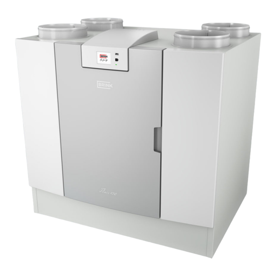
3 Version 3.1 Technical information Flair 450 Flair 450 Supply voltage [V/Hz] 230V/50Hz Dimensions (w x h x d) [mm] 850 x 800 x 660 Duct diameter [mm] ø200 Ext. diameter condensate discharge [mm] ø32 Weight [kg] Filter class ISO Coarse 60% (ISO ePM1.0 50% for the air supply optional) Fan setting (factory setting) Factory setting [m³/h]... -
Page 8: Technical Information Flair 600
*) Duct noise including end correction In practice the value may differ by 1dB(A) through measurement tolerances. Resistance of duct Note: system [Pa] The stated value in the circle is the capacity (in Watt) per fan. Flow rate [m Flair 450/600 616971-A... -
Page 9: Connections And Dimensions
All dimensions in millimeters. Diameter of all collars is 200 mm Supply air Exhaust air Extract air Outdoor air Electrical connections Siphon connection Sealing cap unused condensate discharge connection; do not remove! Extract air filter Supply air filter Mounting bracket Flair 450/600 616971-A Brink / 9... - Page 10 All dimensions in millimeters. Diameter of all collars is 200 mm To dwelling Exhaust air Extract air Outdoor air Electrical connections Siphon connection Sealing cap unused condensate discharge connection; do not remove! Extract air filter Supply air filter Mounting bracket Flair 450/600 616971-A...
-
Page 11: Exploded View Of Appliance
Signal output (X19) ) Temperature sensor (2x) 24 volt connector (X18) Supply filter eBus connector (X17) Exhaust fan 24 volt connector (X16) Siphon Modbus/ internal bus connector (X15) Supply fan Multiple switch connector (X14) Flair 450/600 616971-A Brink / 11... -
Page 12: Operation
For external control a 4-way switch (® Connecting extra multiple switch with filter indication page 41) can, for example, be chosen, but control is also possible with the Brink Air Control (® Connecting Brink Air Control page 43), CO sensor(s) (®... -
Page 13: Frost Protection
1 = For example a Flair 325 and a Flair 225 appliance with mounted Basic pcb 2 = Optional Plus pcb mounting plate 3 = Optional Plus pcb 4 = Optional Plus pcb cover Flair 450/600 616971-A Brink / 13... -
Page 14: Installation
5.2 Placing the appliance The Flair 450/600 appliance can be mounted onto a wall with the supplied mounting bracket. For a vibration-free installation, the appliance must be mounted to a solid wall with a minimum mass of 170 kg/m . -
Page 15: Connecting The Condensate Discharge
With the Flair 450/600 appliance as the left-hand version, the condensate discharge connection is located at the right side of the bottom panel and with the Flair 450/600 appliance as the right- hand version, the condensate discharge connection is located on the left of the bottom panel ( ®... -
Page 16: Connecting Air Ducts
The location of the supply valves must be chosen in such a way to prevent fouling and drafts. We recommend using Brink supply valves. When using flexible mufflers, account must be taken during the installation that these may need to be replaced after a period of time. -
Page 17: Electrical Connections
1 = Flair 450/600 right-hand version (place level) 2 = Preferred location oudoor air inlet 3 = Sewer vent 4 = Preferred location Exhaust air outlet; Use Brink insulated ventilation roof terminal 5 = Thermally insulated ducts 6 = Condensate discharge... -
Page 18: Connecting An Ebus Accessory
Electrical diagram page 36); for more information and the correct modBus settings see the separate Modbus manual on the Brink website! Note: When ModBus is active, the ventilation mode cannot be changed using the display or, if applicable, the connected multiple switch! Also any connected humidity sensor will not function. -
Page 19: Coupling Appliances Using Internal Bus
Bus. All Flair 450/600 appliances have the same air flow rate as the appliance that is set as "Master". The fault messages of all appliances are shown on the display of the master appliance and shown on the display of the relevant appliance. -
Page 20: Display
The factory setting of the menu is English. The desired language/ date & time can be modified in the settings menu ;for this, please refer to the settings value table (® Setting values page 52) step number 15.1 to step number 15.10. Flair 450/600 616971-A... -
Page 21: Display Layout
"Filter cleaning" (® Cleaning filters page 30) for more information. This symbol is only shown if a fault has occurred in the appliance; see chapter Faults (® Fault analysis page 27) for more information. Flair 450/600 616971-A Brink / 21... - Page 22 This appliance is set as Master appliance if a number of appliances are connected (cascade) Appliance is set as Slave appliance; maximum of 9 appliances can be connected to a Master. Control via eBus for example Brink Air Control . Control via ModBus or internal Bus.
- Page 23 Zone Symbol on display Description Internet connection/Network connection Signal strength USB connection active. 11:07 Current set time of the device. 02.01.2020 Current date. Flair 450/600 616971-A Brink / 23...
-
Page 24: Display Information
The touchscreen can also be permanently set as multiple switch; to do this step number 15.8 in the settings menu has to be set to “yes”. Warning: Incorrect settings can seriously disrupt the proper functioning of the appliance! Flair 450/600 616971-A... -
Page 25: Starting Appliance
Good ventilation contributes to healthy air in the home, optimal comfort and the proper functioning of the installation. The air flows of the appliance Flair 450 have been set in the factory as follows 75, 100, 200 and 300 m /h; the air flows of the appliance Flair 600 have been set in the factory as follows 100, 150, 300 and 500 m /h . -
Page 26: Other Settings For Installer
Warning: As changes in the settings menu can disrupt the proper functioning of the appliance, changes of settings not described here require consultation with Brink Climate Systems B.V. Incorrect settings may seriously affect the proper performance of the appliance! 7.4 Factory settings It is possible to simultaneously revert all the changed settings back to the factory settings. -
Page 27: Fault
Contact the installer to remedy this fault. 1. Supply fan defective A locking fault cannot be remedied by taking the voltage from the appliance; first the fault has to be solved. Flair 450/600 616971-A Brink / 27... - Page 28 1 E130 E1800 Relay output 1 defective; Signal output not Take voltage from appliance general fault available Replace UWA2-B pcb Fault is automatically reset when voltage is again put back on appliance. Flair 450/600 616971-A...
- Page 29 Brink Air Control Check wiring to accessories/ Brink Air Control message and other Check accessories/ Brink Air Control and replace if defective accessories do If there is still a fault after this: Take voltage from appliance not work. and replace basic pcb UWA2-B...
-
Page 30: Maintenance
" return" button The timer of the filter message is then reset! Pressing the Home button brings you back to the main screen from any particular menu; pressing the return button takes you back 1 step in the menu. Flair 450/600 616971-A... -
Page 31: Maintenance Siphon
9.2 Maintenance siphon Cleaning the siphon Every year the siphon must be disconnected and cleaned. (For example a Flair 325 appliance type 4-0). Flair 450/600 616971-A Brink / 31... -
Page 32: Maintenance Installer
Installer maintenance includes cleaning the heat exchanger, internal preheater and fans. Dependent on the conditions, this must done about once every three years. Remove the power supply by pulling out the plug. Open the filter door. Remove the two filters. Remove the front cover. Flair 450/600 616971-A... - Page 33 Wash the heat exchanger with hot water (max. 45°C) and a regular detergent. Then rinse the exchanger with hot water. Take EPS assembly, with which the fan is inserted into the appliance, out of the appliance. Flair 450/600 616971-A Brink / 33...
- Page 34 Turn the fan a quarter of a revolution in the appliance. Tilt the fan in such a way that this can be taken out of the EPS assembly; disconnect both fan cables from the fan. Now take the fan out of the appliance. Flair 450/600 616971-A...
- Page 35 Reset the timer of the filter message by setting the timer back to zero in the settings menu at step number 4.3. After resetting the timer of the filter message the appliance returns to the main menu and the appliance is once again ready for use. Flair 450/600 616971-A Brink / 35...
-
Page 36: Electrical Diagram
10 Electrical diagram Flair 450/600 616971-A... - Page 37 USB stick for updating software (not supplied with appliance) X18 = 24V (max 5VA) Service connector X19 = Signal output Laptop with installed Brink service tool (not supplied) Plus pcb Touchscreen on appliance Valve motor bypass valve X03 = 24V...
-
Page 38: Electrical Connections Accessories
It is best to use a 4-way switch with filter indication; always install an RJ12 connector in combination with a 6- core modular cable. When using a 3-way switch without filter indication always install an RJ11 connector in combination with a 4-core modular cable. Flair 450/600 616971-A... -
Page 39: Connecting Multiple Switch With Filter
C = Modular cable: Note: For the modular cable that is used, the “tab” of both modular connectors must be mounted facing the mark on the modular cable. Wire colors C1 - C6 may vary dependent on the type of modular cable used. Flair 450/600 616971-A Brink / 39... -
Page 40: Filter Indication)
F = Modular cable: Note: For the modular cable that is used, the “tab” of both modular connectors must be mounted facing the mark on the modular cable. Wire colors C1 - C6 may vary dependent on the type of modular cable used. Flair 450/600 616971-A... -
Page 41: Connecting Extra Multiple Switch With Filter
= Modular cable: Note: For the modular cable that is used, the “tab” of both modular connectors must be mounted facing the mark on the modular cable. Wire colors C1 - C6 may vary dependent on the type of modular cable used. Flair 450/600 616971-A Brink / 41... -
Page 42: Connecting Extra Multiple Switch With Filter
F = Modular cable: Note: For the modular cable that is used, the “tab” of both modular connectors must be mounted facing the mark on the modular cable. Wire colors C1 - C6 may vary dependent on the type of modular cable used. Flair 450/600 616971-A... -
Page 43: Connecting Brink Air Control
11.2 Connecting Brink Air Control A = Flair appliance (For example a Flair 325 appliance type 4-0) B = Brink Air Control (option) C = Two-core control cables D = Green two-pole screw connector E = Position green eBus connector to rear of control... -
Page 44: Connecting Humidity Sensor
4 = The cable that comes with RH cable 5 = RH (humidity) sensor 6 = Duct from dwelling To switch on and set the sensitivity of the humidity sensor, go to step number 7.1 and 7.2 in the settings menu Flair 450/600 616971-A... -
Page 45: Connecting Co₂ Sensor(S)
6.1 in the settings menu ; in order to set the minimum and maximum PPM value of the CO sensor(s) set, if necessary, the right values following step numbers 6.2 to 6.9. Flair 450/600 616971-A Brink / 45... -
Page 46: Connecting Postheater
C2 = blue 4 = Temperature sensor C3 = green/yellow C4 = black 5 = PCB type UVP1 C5 = white 6 = Airflow direction 7 = Dipswitch setting Flair postheater (For example a Flair 325 appliance type 4-0) Flair 450/600 616971-A... -
Page 47: Connecting Preheater
4 = Temperature sensor C3 = green/yellow C4 = black 5 = PCB type UVP1 C5 = white 6 = Airflow direction 7 = Dipswitch setting Flair preheater (For example a Flair 325 appliance type 4-0) Flair 450/600 616971-A Brink / 47... -
Page 48: Connecting Geo-Heat Exchanger
0.0 °C / 10.0 °C 11.3 Switch temperature 2 25°C 15.0°C / 40.0 °C 11.4 Mode valve 10 volt control Closed Open / Closed Relay output 1/Relay output 2/ 11.5 Valve control Relay output 1 Analogue output 1/Analogue output 2 Flair 450/600 616971-A... -
Page 49: Service
N.B.: Appliance type, serial number and year of production are stated on the identification plate behind the plastic front panel on the appliance. Example Appliance type Flair 450 Serial number 432000221201 Year of production 2022 Part Article code 533037 Quantity Flair 450/600 616971-A Brink / 49... -
Page 50: Service Articles
12.2 Service articles Flair 450/600 616971-A... - Page 51 Article description Article code Front panel complete Flair 450 532828 Front panel complete Flair 600 532826 Filters (2 items) ISO Coarse 60% 532811 Heat exchanger 532885 Fan (1 item) 533037 Cable set 532891 Temperature sensor NTC 10K (1 item) 531775...
-
Page 52: Setting Values
13 Setting values 13.1 Setting values standard appliance The below setting values are for a Flair 450/600-appliance without Plus pcb. Step Description Factory settings Setting range Comment Flow rate Flair 450 Air flow rate setting 0 75 m³/h 0 or adjustable between 75 m³/h and 450 m³/h (never higher than step no. - Page 53 Sensitivity of humidity sensor +2 = most sensitive 0 = basic setting -2 = least sensitive Cascade 0 / 9 Appliance setting 0 (Master) (0=Master; 1 t/m 9 = Slave 1 t/m Slave 9) Flair 450/600 616971-A Brink / 53...
- Page 54 Yes / No 15.10 Fan position wizard Yes / No Signal output Off / Only filter condition / Only fault Connector X19 16.1 Signal output condition / Filter and fault condition Standby 17.1 Switch off appliance Yes / No Flair 450/600 616971-A...
-
Page 55: Setting Values Appliance With Plus Pcb
13.2 Setting values appliance with Plus pcb The below setting values are for a Flair 450/600-appliance with Plus pcb. Step Description Factory settings Setting range Comment Switch contacts Make or break contact 1 Make Make / Break Switch contact control 1... - Page 56 Switch temperature 2 25 °C 15.0°C / 40.0 °C 11.4 Mode valve 24 volt control Closed Open / Closed 11.5 Valve control Relay output 1 Relay output 1/ Relay output 2/ Analogue output 1/ Analogue output 2 Flair 450/600 616971-A...
-
Page 57: Conformity Declaration
14 Conformity declaration Manufacturer: Brink Climate Systems B.V. P.O. Box 11 Address: NL-7950 AA, Staphorst, The Netherlands Product: Heat recovery appliance type: Flair 450 Flair 600 The product described above complies with the following directives: ¨ 2014/35/EU (OJEU L 96/357; 29-03-2014) (OJEU L 96/79;... -
Page 58: Erp Values Flair 450
External 0.90% Position dirty filter On the display of the appliance / on the multiple switch (LED) / on the Brink Air Control. Attention! For optimal energy efficiency and a proper operation, a regular filter inspection, indication: cleaning or replacement is necessary. - Page 59 A+ (Most efficient) SEC < -42 -42 ≤ SEC < -34 -34 ≤ SEC < -26 -26 ≤ SEC < -23 -23 ≤ SEC < -20 E (Least efficient) -20 ≤ SEC < -10 Flair 450/600 616971-A Brink / 59...
-
Page 60: Erp Values Flair 600
External 0.70% Position dirty filter On the display of the appliance / on the multiple switch (LED) / on the Brink Air Control. Attention! For optimal energy efficiency and a proper operation, a regular filter inspection, indication: cleaning or replacement is necessary. - Page 61 A+ (Most efficient) SEC < -42 -42 ≤ SEC < -34 -34 ≤ SEC < -26 -26 ≤ SEC < -23 -23 ≤ SEC < -20 E (Least efficient) -20 ≤ SEC < -10 Flair 450/600 616971-A Brink / 61...
-
Page 62: Recycling
17 Recycling Recycling Sustainable materials are used in the manufacture of this appliance. The packaging should be disposed of in a responsible manner and in accordance with governmental regulations. Flair 450/600 616971-A... - Page 64 Brink Climate Systems B.V. P.O. Box 11, NL-7950AA Staphorst T: +31 (0) 522 46 99 44 E: info@brinkclimatesystems.nl www.brinkclimatesystems.nl...
Need help?
Do you have a question about the Flair 450 and is the answer not in the manual?
Questions and answers