Brink Flair 325 Installation Regulations
Hide thumbs
Also See for Flair 325:
- Installation regulations (60 pages) ,
- Installation regulations (64 pages) ,
- Installation regulations (57 pages)
Table of Contents
Advertisement
Advertisement
Table of Contents

Related Manuals for Brink Flair 325


Summary of Contents for Brink Flair 325
- Page 1 Installation regulations Flair 325 English...
- Page 3 Children may not play with the appliance. If you need a new power cable, always order the replacement from Brink Climate Systems B.V. To prevent dangerous situations, a damaged mains connection must only...
-
Page 4: Table Of Contents
1 Delivery........5 11.2 Connecting Brink Air Control....42 1.1 Delivery size. -
Page 5: Delivery
2. Wall mounting bracket consisting of: ▪ 1x mounting bracket ▪ 2x protective caps ▪ 2x rubber strip ▪ 2x rubber rings 3. Siphon 4. Documentation set consisting of: ▪ 1x installation instructions ▪ 1x occupant's instructions Flair 325 615674-D Brink / 5... -
Page 6: General
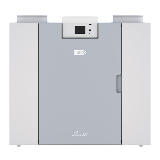
2 General The Flair 325 and the Flair 325 Plus is a ventilation unit for the balanced ventilation of dwellings with heat recovery. Features: ▪ Maximum capacity 325 m³/h ▪ High return plastic heat exchanger ▪ Filters ISO Coarse 60% ▪... -
Page 7: Version
3 Version 3.1 Technical information Flair 325 (Plus) Supply voltage [V/Hz] 230V/50Hz Dimensions (w x h x d) [mm] 750 x 650 x 560 Duct diameter [mm] ø160 External diameter condensate discharge [mm] ø32 Weight [kg] Filter class ISO Coarse 60% (ISO ePM1.0 50% for the air supply optional) Fan setting (factory setting) Factory setting [m³/h]... -
Page 8: Connections And Dimensions
(1 & 3) are on the right-hand side of the appliance. Left-hand version All dimensions in millimeters. Diameter of all collars is 160 mm To dwelling To outside From dwelling From outside Electrical connections Siphon connection Exhaust air filter Supply air filter Mounting Flair 325 615674-D... - Page 9 Right-hand version All dimensions in millimeters. Diameter of all collars is 160 mm To dwelling To outside From dwelling From outside Electrical connections Siphon connection Exhaust air filter Supply air filter Mounting Flair 325 615674-D Brink / 9...
-
Page 10: Exploded View Of Appliance
Power cable 230 volt Preheater Relay output (X19) ) Temperature sensor 24 volt connector (X18) Supply filter eBus connector (X17) Exhaust fan 24 volt connector (X16) Siphon connector Modbus/ Brinkbus connector (X15) Supply ventilator Multiple switch connector (X14) Flair 325 615674-D... -
Page 11: Operation
For external control a 4-way switch (® Connecting extra multiple switch with filter indication page 40) can, for example, be chosen, but control is also possible with the Brink Air Control (® Connecting Brink Air Control page 42), CO sensor(s) (®... -
Page 12: Frost Protection
WiFi signal from the Plus pcb. A standard heat recovery appliance can also later be modified into a Plus version using the Plus pcb upgrade set. 1 = Flair 325 appliance with mounted Basic pcb 2 = Plus pcb mounting plate... -
Page 13: Installation
5.2 Placing the appliance The Flair 325 (Plus) appliance can be mounted onto the wall with the supplied mounting bracket. For a vibration- free installation, the appliance must be mounted to a solid wall with a minimum mass of 200 kg/m . -
Page 14: Connecting The Condensate Discharge
5.3 Connecting the condensate discharge The condensate discharge line for the Flair 325 appliance is located in the lower panel. The condensate is discharged through the drainpipe. The siphon (with built-in aerator) is supplied separately with the appliance and must be fitted by the installer below the appliance (bayonet connection). The siphon has an external connection diameter of 32 mm. -
Page 15: Connecting Air Ducts
Brink input valves. When using flexible mufflers, account must be taken during the installation that these may need to be replaced after a period of time. Install sufficient overflow openings, door gap 2 cm. Flair 325 615674-D Brink / 15... -
Page 16: Electrical Connections
1 = Flair 325 right-hand version (place level) 2 = Preferred ventilation air supply 3 = Sewer release 4 = Preferred location of ventilation air discharge; Use Brink insulated ventilation roof sleeve 5 = Thermally insulated piping 6 = Condensater discharge... -
Page 17: Connecting The Ebus Connector
Exploded view of appliance page 10). The eBus protocol may for instance be used to connect the Brink Air Control (® Connecting Brink Air Control page 42). Because of polarity sensitivity, always connect contacts correctly; the appliance will not work if these... -
Page 18: Coupling Appliances Using Brinkbus
Comment: If a Plus pcb has been installed; several cables would have to be connected onto the X-15 connector. Note: When the total length of the Brink Bus cables is longer than 10 m, then use a twisted-pair cable for connection X15-2 & X15-3 (a twisted pair cable is also preferred with shorter lengths)! -
Page 19: Display
The desired language/ date & time can be modified in the settings menu ;for this, please refer to the settings value table (® Setting values page 51) step number 15.1 to step number 15.10. Flair 325 615674-D Brink / 19... -
Page 20: Display Layout
Filter message symbol; this is only shown if the filter has to be cleaned or replaced. See chapter "Filter cleaning" (® Cleaning filter page 30) for more information. This symbol is only shown if a fault has occurred in the appliance; see chapter Faults (® Fault analysis page 26) for more information. Flair 325 615674-D... - Page 21 This appliance is set as Master appliance if a number of appliances are connected (cascade) Appliance is set as Slave appliance; maximum of 9 appliances can be connected to a Master. Control via eBus for example Brink Air Control . Control via ModBus or BrinkBus.
- Page 22 Zone Symbol on display Description Internet connection Signal strength USB connection active. 11:07 Current time. 02.11.17 Current date. Flair 325 615674-D...
-
Page 23: Display Information
The touchscreen can also be permanently set as multiple switch; to do this step number 15.6 in the settings menu has to be set to “yes”. Warning: Incorrect settings can seriously disrupt the proper functioning of the appliance! Flair 325 615674-D Brink / 23... -
Page 24: Starting Appliance
An exception to this is ventilator mode 0. If mode 0 is chosen on the display: control from other switches, sensors, etc. is not possible. Flair 325 615674-D... -
Page 25: Other Settings For Installer
Warning: As changes in the settings menu can disrupt the proper functioning of the appliance, changes of settings not described here require consultation with Brink Climate Systems B.V. Incorrect settings may seriously affect the proper performance of the appliance! 7.4 Factory settings It is possible to simultaneously revert all the changed settings back to the factory settings. -
Page 26: Fault
Press the fault symbol for an explanation/ solution to the fault. The screen can be left by pressing the "Home" button. If a fault cannot be solved, please contact the installer. 1. Requested supply flow rate is not reached Flair 325 615674-D... - Page 27 (NTC) E105 * E1100 * Supply fan defective; Appliance goes Replace supply fan general message to standby Fault is reset automatically when voltage is put back on appliance. Flair 325 615674-D Brink / 27...
- Page 28 Brink Air Control Check wiring to accessories/ Brink Air Control message and other Check accessories/ Brink Air Control and replace if defective accessories do If there is still a fault after this: Take voltage from appliance and not work. replace basic pcb UWA2-B...
- Page 29 Uncouple postheater and check postheater fuse; replace fuse if fuse defective; general comfort control defective fault message responds Has the fault not yet been remedied: differently Replace external postheater Put voltage back on appliance Fault has automatically been reset Flair 325 615674-D Brink / 29...
-
Page 30: Maintenance
" return" button The timer of the filter message is then reset! Pressing the Home button brings you back to the main screen from any particular menu; pressing the return button takes you back 1 step in the menu. Flair 325 615674-D... -
Page 31: Maintenance
Installer maintenance includes cleaning the heat exchanger and fans. Dependent on the conditions, this must done about once every three years. Remove the power supply by pulling out the plug. Open the filter door. Remove the two filters. Remove the front cover. Flair 325 615674-D Brink / 31... - Page 32 Remove the heat exchanger. Be careful not to damage the foam parts in the appliance. Wash the heat exchanger with hot water (max. 45°C) and a regular detergent. Then rinse the exchanger with hot water. Take EPS assembly, with which the fan is inserted into the appliance, out of the appliance. Flair 325 615674-D...
- Page 33 Turn the fan a quarter of a revolution in the appliance. Tilt the fan in such a way that this can be taken out of the EPS assembly; disconnect both fan cables from the fan. Now take the fan out of the appliance. Flair 325 615674-D Brink / 33...
- Page 34 Reset the timer of the filter message by setting the timer back to zero in the settings menu at step number 4.3. After resetting the timer of the filter message the appliance returns to the main menu and the appliance is once again ready for use. Flair 325 615674-D...
-
Page 35: Electrical Diagram
10 Electrical diagram Flair 325 615674-D Brink / 35... - Page 36 5 = USB stick for updating software (not supplied with appliance) X18 = 24V (max 5VA) 6 = Service connector X19 = Signal output 7 = Laptop with installed Brink service tool (not supplied) Plus pcb UWA2-E 8 = Touchscreen on appliance 9 = Valve motor bypass valve...
-
Page 37: Electrical Connections Accessories
It is best to use a 4-way switch with filter indication; always install an RJ12 connector in combination with a 6- core modular cable. When using a 3-way switch without filter indication always install an RJ11 connector in combination with a 4- core modular cable. Flair 325 615674-D Brink / 37... -
Page 38: Connecting Position Switch With Filter
11.1.1 Connecting position switch with filter indication Flair 325 appliance 4-way switch with filter indication Modular cable: Note: For the modular cable that is used, the “tab” of both modular connectors must be mounted facing the mark on the modular cable. Wire colors C1 - C6 may vary dependent on the type of modular cable used. -
Page 39: Connecting Wireless Remote Control
11.1.2 Connecting wireless remote control (without filter indication) A = Flair 325 appliance B = Receiver for wireless remote control C = Transmitter with 4 settings (for example kitchen) D = Transmitter with 2 settings (for example bathroom) E = Any additional 2- or 4-settings transmitters (maximum of 6 transmitters can be signed on to 1 receiver) = Modular cable: Note: For the modular cable that is used, the “tab”... -
Page 40: Indication
11.1.3 Connecting extra multiple switch with filter indication = Flair 325 appliance B1 = Multiple switch with filter indication B2 = Extra multi switch with filter indication = Splitter = Modular cable: Note: For the modular cable that is used, the “tab” of both modular connectors must be mounted facing the mark on the modular cable. -
Page 41: Indication
11.1.4 Connecting extra multiple switch with filter indication A = Flair 325 appliance B = Multiple switch with filter indication C = Receiver for wireless remote control D = Transmitter with 2 settings or 4 settings E = Splitter = Modular cable: Note: For the modular cable that is used, the “tab” of both modular connectors must be mounted facing the mark on the modular cable. -
Page 42: Connecting Brink Air Control
11.2 Connecting Brink Air Control A = Flair appliance B = Brink Air Control (option) C = Two-core control cables D = Green two-pole screw connector E = Position green eBus connector to rear of control Flair 325 615674-D... -
Page 43: Connecting Humidity Sensor
4 = The cable that comes with RH cable 5 = RH (humidity) sensor 6 = Duct from dwelling To switch on and set the sensitivity of the humidity sensor, go to step number 7.1 and 7.2 in the settings menu Flair 325 615674-D Brink / 43... -
Page 44: Connecting Co₂ Sensor(S)
6.1 in the settings menu ; in order to set the minimum and maximum PPM value of the CO sensor(s) set, if necessary, the right values following step numbers 6.2 to 6.9. Flair 325 615674-D... -
Page 45: Demand-Driven Ventilation 2.0
1 = Zone valve demand-driven ventilation C1 =brown 2 = Power 24 VDC C2 = blue C3 = green/yellow 3 = Brink Air Control C5 = white 4 = Valve motor zone valve C10 = yellow 5 = EBus connection X17 on Flair appliance... -
Page 46: Connecting Postheater
C3 = green/yellow 3 = 2-pole eBus connection X17 on Flair aplliance C4 = black 4 = Temperatur sensor C5 = white 5 = PCB type UVP1 6 = Airflow direction 7 = Dipswitch setting Flair postheater Flair 325 615674-D... -
Page 47: Connecting Preheater
3 = 2-pole eBus connection X17 on Flair appliance C4 = black 4 = Temperatur sensor C5 = white 5 = PCB type UVP1 6 = Airflow direction 7 = Dipswitch setting Flair preheater Flair 325 615674-D Brink / 47... -
Page 48: Service
N.B.: Appliance type, serial number and year of production are stated on the identification plate behind the plastic front panel on the appliance. Example Appliance type Flair 325 Plus Serial number 430000191201 Year of production 2019... -
Page 49: Service Articles
12.2 Service articles Flair 325 615674-D Brink / 49... - Page 50 The power cable is fitted with a circuit board connector. When replacing it, always order a replacement mains cable from Brink. To prevent dangerous situations, a damaged mains connection can only be replaced by a qualified expert. Flair 325 615674-D...
-
Page 51: Setting Values
13 Setting values 13.1 Setting values standard appliance The below setting values are for a Flair 325-appliance without Plus pcb. Step Description Factory settings Setting range Comment Flow rate Air flow rate setting 0 50 m³/h 0 or adjustable between 50 m³/h and 325 m³/h (never higher than step no. - Page 52 (0=Master; 1 t/m 9 = Slave 1 t/m Slave 9) Central heating + heat recovery 12.1 Status On / Off Communication 14.1 Type of Bus connection ModBus Off / BrinkBus/ ModBus 14.2 Slave address 1 - 247 For Modbus Flair 325 615674-D...
- Page 53 15.10 Fan position wizard Yes / No Signal output 16.1 Signal output Off / Only filter condition / Only fault Connector X19 condition / Filter and fault condition Standby 17.1 Switch off appliance Yes / No Flair 325 615674-D Brink / 53...
-
Page 54: Setting Values Appliance With Plus Pcb
13.2 Setting values appliance with Plus pcb The below setting values are for a Flair 325-appliance with Plus pcb. Step Description Factory settings Setting range Comment Switch contacts Make or break contact 1 Make Make / Break Switch contact control 1... - Page 55 25 °C 15.0°C / 40.0 °C 11.4 Mode valve 10 volt control Closed Open / Closed 11.5 Valve control Relay output 1 Relay output 1/ Relay output 2/ Analogue output 1/ Analogue output 2 Flair 325 615674-D Brink / 55...
-
Page 56: Conformity Declaration
14 Conformity declaration Conformity declaration Manufacturer: Brink Climate Systems B.V. Address: Postbus 11 NL-7950 AA, Staphorst, The Netherlands Product: Heat recovery appliance type: Flair 325 Flair 325 Plus The product described above complies with the following directives: ¨ 2014/35/EU (low voltage directive) ¨... -
Page 57: Erp Values
15 ERP values Technical information sheet Flair 325 (Plus) in accordance with Ecodesign (ErP), no. 1254/2014 (Annex IV) Manufacturer: Brink Climate Systems B.V. Model: Flair 325 (Plus) Climate Type of control SEC Value Annual Annual heating zone Class electricity saved (AHS) in kWh/m²/a... - Page 58 SEC in kWh/m²/a A+ (Most efficient) SEC < -42 -42 ≤ SEC < -34 -34 ≤ SEC < -26 -26 ≤ SEC < -23 -23 ≤ SEC < -20 G (Least efficient) -20 ≤ SEC < -10 Flair 325 615674-D...
-
Page 59: Recycling
16 Recycling Recycling Sustainable materials are used in the manufacture of this appliance. The packaging should be disposed of in a responsible manner and in accordance with governmental regulations. Flair 325 615674-D Brink / 59... - Page 60 Brink Climate Systems BV E info@brinkclimatesystems.com P.O. Box 11 NL-7950AA Staphorst www.brinkclimatesystems.com T +31 (0) 522 46 99 44 www.brinkairforlife.com...
Need help?
Do you have a question about the Flair 325 and is the answer not in the manual?
Questions and answers