Table of Contents
Advertisement
Available languages
Available languages
Quick Links
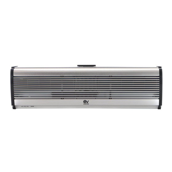
Scheda Tecnica
CODICE 65156
AIR DOOR H AD900 T
Barriere d'aria
DATI TECNICI E PRESTAZIONALI
Corrente assorbita max (A)
Frequenza (Hz)
Numero velocità
Peso (Kg)
Potenza max assorbita alla max vel. (W)
Potenza max assorbita alla min vel. (W)
Temp. ambiente max funzionamento
continuativo (°C)
Tensione (V)
1° Potenza (W)
DIMENSIONI
PER INFORMAZIONI:
Servizio al Cliente: tel +39 02 90699395 premendo 1 dopo messaggio registrato (consulenza su prodotti e impianti)
Pre & Post Vendita: fax +39 02 90699302
Email prevendita: prevendita@vortice-italy.com
26.5
2° Potenza (W)
50
3° Potenza (W)
2
Portata max alla max vel. (l/s)
13.5
Portata max alla max vel. (m³/h)
6160
Portata max alla min vel. (l/s)
6110
Portata max alla min vel. (m³/h)
25
Pressione sonora Lp [dB (A)] 2m - max
vel.
400
Pressione sonora Lp [dB (A)] 2m - min
vel.
2000
Velocità aria alla max vel. (m/s)
Velocità aria alla min vel. (m/s)
Dimensione A (mm)
Dimensione B (mm)
Dimensione C (mm)
Etichetta Energetica
Certificazioni
C E
4000
6000
333
1200
278
1000
57
55
9.5
8.5
900
260
190
NO
Advertisement
Table of Contents

Related Manuals for Vortice AIR DOOR H


Summary of Contents for Vortice AIR DOOR H
- Page 1 Scheda Tecnica CODICE 65156 AIR DOOR H AD900 T Barriere d'aria Certificazioni DATI TECNICI E PRESTAZIONALI Corrente assorbita max (A) 26.5 2° Potenza (W) 4000 Frequenza (Hz) 3° Potenza (W) 6000 Numero velocità Portata max alla max vel. (l/s) Peso (Kg) 13.5...
- Page 2 Servizio al Cliente: tel +39 02 90699395 premendo 1 dopo messaggio registrato (consulenza su prodotti e impianti) Pre & Post Vendita: fax +39 02 90699302 Email prevendita: prevendita@vortice-italy.com Scheda Tecnica CODICE 65156 AIR DOOR H AD900 T Barriere d'aria DESCRIZIONE • Lunghezza nominale: 900 mm. sovratemperature e i picchi di tensione, caratterizzata da un’elevata •...
- Page 3 Libretto istruzioni Instruction booklet Notice d’emploi et d’entretien Betriebsanleitung Manual de instrucciones AIR DOOR H COD. 5471.084.161 22/12/2014...
-
Page 4: Table Of Contents
Safety ......9 Vortice is not liable for damage or injury Sizes ......10 resulting from failure to follow the instructions Installation . - Page 5 Seguridad ......24 instrucciones. Vortice no se hace responsable de los eventuales daños ocasionados a personas o cosas Dimensiones .
-
Page 6: Descrizione Ed Impiego
La famiglia AIR DOOR H si compone dei seguenti modelli, con portata d’aria crescente: esso inerenti. I bambini non AD900 M devono giocare AD900 T l'apparecchio. -
Page 7: Dimensioni
ITALIANO L’installazione dell’apparecchio • deve essere eseguita personale professionalmente qualificato. Per l’installazione è necessario • prevedere interruttore onnipolare con distanza di apertura dei contatti uguale o superiore a 3 mm. Dimensioni Tabella, fig.1, 2, 3. MODEL 900 440 90 190 105 260 Installazione AD900 M Avvertenze... - Page 8 ITALIANO • installare l’apparecchio a non meno di 2,3 m dal Montaggio suolo (fig. l’accesso è più ampio Rimuovere la piastra di montaggio svitando le viti dell’apparecchio, si raccomanda di installare due o fissate sul retro del corpo centrale (fig.8); più...
- Page 9 ITALIANO C Montaggio a soffitto Fissare le staffe per soffitto come indicato nella fig.14. Rondella Rondella elastica Dado Staffa B Montaggio su parete in legno Fissare la piastra di montaggio nella posizione adeguata con viti filettate: fig. 12. Posizionare la piastra di montaggio sulle staffe utilizzando i bulloni annessi, come illustrato in fig.15.
-
Page 10: Utilizzo
ITALIANO C Montaggio al di sopra del soffitto Informazione importante per lo (controsoffitto) smaltimento ambientalmente Fissare la barriera d’aria eseguendo lo stesso procedimento dell’installazione su parete in compatibile calcestruzzo. Effettuare i collegamenti delle tubazioni secondo quanto riportato in fig.17. IN ALCUNI PAESI DELL'UNIONE EUROPEA QUESTO PRODOTTO NON RICADE NEL CAMPO DI APPLICAZIONE DELLA LEGGE NAZIONALE DI RECEPIMENTO DELLA DIRETTIVA RAEE E... -
Page 11: Description And Use
The AIR DOOR H family consists of the following models, in order of airflow: the hazards involved. Children AD900 M... -
Page 12: Sizes
ENGLISH used to install the appliance. The contact opening gap must be no less than 3 mm. Sizes Table, fig.1, 2, 3. MODEL 900 440 90 190 105 260 AD900 M 900 440 90 190 105 260 AD900 T 1200 840 90 190 105 260 Installation AD1200 T 1500 840 90 190 105 260... - Page 13 ENGLISH • install the appliance at least 2.3 m from the floor. Mounting (fig. 6); If the access area is larger than the Remove the mounting plate by loosening the screws appliance, we recommend installing two or more fixed to the back of the central body (fig.8). units in parallel;...
- Page 14 ENGLISH C Mounting on the ceiling Fix the ceiling brackets in place, as indicated in the fig.14. Washer Elastic washer Bracket B Mounting on wooden walls Fix the mounting plate in the right position using threaded screws (fig.12). Position the mounting plate on the brackets using the attached bolts, as illustrated in the fig.15.
-
Page 15: Operation
ENGLISH C Mounting above the ceiling (false ceiling) Important information on eco- Fix the air curtain in place using the same compatible disposal installation procedure as for concrete walls. Connect the pipes as shown in the fig.17. IN CERTAIN EUROPEAN UNION COUNTRIES THIS PRODUCT DOES FALL... -
Page 16: Description Et Mode D'emploi
La gamme des AIR DOOR H se compose des les instructions d'utilisation de modèles suivants, par débit d'air croissant : AD900 M l'appareil en toute sécurité, et... -
Page 17: Dimensions
FRANCAIS correspondre à celles qui sont inscrites sur la plaquette appliquée sur l'appareil. L’installation de l'appareil doit • être réalisée par un technicien qualifié. Pour l'installation de l'appareil, • prévoir interrupteur omnipolaire ayant une distance d'ouverture entre les contacts égale ou supérieure à 3 mm. Dimensions Tableau, fig.1, 2, 3. - Page 18 FRANCAIS • Installer l’appareil à 2,3 m du sol minimum (fig. 6); si Montage l'accès concerné est plus large que l'appareil, il est Ôter la plaque de montage et les vis fixées à l'arrière recommandé d'installer deux unités ou plus en du corps central (fig.8).
- Page 19 FRANCAIS C Montage au plafond Fixer les attaches pour plafond comme le montre la fig. 14. Rondelle Rondelle elastique Ecrou Etrier B Montage sur une cloison en bois Fixer la plaque de montage dans la position adéquate avec des vis filetées (fig. 12). Positionner la plaque de montage sur les étriers en utilisant les boulons joints, comme le montre la figure suivante.
-
Page 20: Mode D'emploi
FRANCAIS C Montage dans un faux-plafond Information importante pour Fixer le rideau d'air en suivant la même procédure éliminer l’appareil en respec- d'installation que pour les murs en béton. Raccorder les tubes comme le montre la fig. 17 tant l’environnement DANS CERTAINS PAYS... -
Page 21: Beschreibung Und Gebrauch
Krankenhäusern und Labors, in Gastronomie- und Kinder Jahren Empfangsbereichen, in Cafés und Restaurants sowie • in Läden im Allgemeinen. Personen mit eingeschränkten Die Gerätefamilie AIR DOOR H setzt sich aus den körperlichen, sensorischen oder folgenden Modellen steigender Leistung zusammen: geistigen Fähigkeiten... -
Page 22: Abmessungen
• Die Ansaug- und Ausblasgitter des Geräts stets freihalten. • Fällt das Gerät hinunter oder wurde es starken Stößen ausgesetzt, muss es sofort vom Vortice- Vertragskundendienst überprüft werden. • Bei Betriebsstörungen und/oder defektem Gerät sofort den Vortice-Vertragskundendienst aufsuchen und für eine eventuelle Reparatur die Verwendung von Vortice-Originalersatzteilen verlangen. - Page 23 DEUTSCH • Das Gerät immer im Rauminnern installieren (Abb. Montage Die Schrauben an der Rückseite des mittleren Geräteteils lösen und die Montageplatte entfernen (Abb.8); Lufteinlass Montageplatte Intern Extern Luftaustritt Befestigungsschraube • Das Gerät auf mindestens 2,3 m Höhe vom Boden installieren (Abb.
- Page 24 DEUTSCH einhängen (Abb.11). Das mittlere Geräteteil wie bereits beschrieben anbringen (Abb.13). B Montage an einer Holzwand Montageplatte Schrauben C Deckenmontage passenden Position befestigen (Abb. 12). Deckenhalterungen nachstehend abgebildet befestigen (Abb. 14). Holzschraube Rondella Rondella elastica Dado Staffa Montageplatte Die Montageplatte mithilfe der beiliegenden Mutterschrauben an den Halterungen positionieren wie nachstehend abgebildet.
-
Page 25: Gebrauch
DEUTSCH Das mittlere Geräteteil wie bereits beschrieben bevor es automatisch abschaltet. anbringen (Abb. 16). Wartung/Reinigung Vor jeder Reinigung oder Wartung das Gerät abschalten und vom Stromnetz trennen. Zur Reinigung des Geräts keine chemischen Produkte wie Petroleum, Benzol, oder Lösungsmittel verwenden. Wasser und andere Flüssigkeiten dürfen nicht in das Gerät gelangen Wichtige information für die umweltgerechte Entsorgung... -
Page 26: Descripción Y Uso
La familia de las AIR DOOR H incluye los siguientes experiencia o del conocimiento modelos, con caudales de aire crecientes: AD900 M necesario, pero sólo... -
Page 27: Dimensiones
ESPAÑOL • Seleccionar un punto de entrada del aire fresco que se encuentre lejos de fuentes contaminantes. • Los datos eléctricos de la red deben coincidir con aquellos indicados en la placa de datos eléctricos del aparato. El aparato debe ser instalado •... - Page 28 ESPAÑOL • Instalar el aparato en el interior de una habitación Montaje (fig. 5); Sacar la placa de montaje desenroscando los tornillos fijados en la parte posterior del cuerpo central (fig.8); Placa de montaje Entrada de aire Interno Externo Salida de aire Tornillo de fijación •...
- Page 29 ESPAÑOL Aplicar el cuerpo central al extremo superior de la C Montaje de techo placa de montaje y engancharlo como se indica en Fijar los soportes de techo como se indica en la la fig.11. figura siguiente (fig.14). Rondana Rondana elastica Nuez Estribo...
-
Page 30: Uso
ESPAÑOL Efectuar las conexiones de los tubos como se Información importante sobre indica en la fig.17. eliminación respetuosa con el medio ambiente EN ALGUNOS PAÍSES DE LA UNIÓN EUROPEA ESTE PRODUCTO NO ESTÁ INCLUIDO EN EL Conducto de aire ÁMBITO DE APLICACIÓN DE LA LEY NACIONAL QUE TRASPONE LA DIRECTIVA RAEE Y, POR LO TANTO, NO EXISTE OBLIGACIÓN ALGUNA DE RECOGIDA SELECTIVA AL FINALIZAR SU VIDA...
Need help?
Do you have a question about the AIR DOOR H and is the answer not in the manual?
Questions and answers