Table of Contents
Advertisement
Quick Links
Advertisement
Table of Contents
Troubleshooting

Related Manuals for Supermicro SuperServer 210P-FRDN6T


Summary of Contents for Supermicro SuperServer 210P-FRDN6T
- Page 1 SuperServer ® 210P-FRDN6T USER’S MANUAL Revision 1.0...
- Page 2 State of California, USA. The State of California, County of Santa Clara shall be the exclusive venue for the resolution of any such disputes. Supermicro's total liability for all claims will not exceed the price paid for the hardware product.
- Page 3 If you have any questions, please contact our support team at: support@supermicro.com This manual may be periodically updated without notice. Please check the Supermicro website for possible updates to the manual revision level. Secure Data Deletion A secure data deletion tool designed to fully erase all data from storage devices can be found on our website: https://www.supermicro.com/about/policies/disclaimer.cfm?url=/wdl/utility/...
-
Page 4: Table Of Contents
Preface Contents Chapter 1 Introduction 1.1 Overview ..........................8 1.2 System Features ........................9 Front View ...........................9 Control Panel .........................11 Rear View ..........................12 1.3 System Architecture ......................13 PCB Locations ........................13 1.4 Motherboard Layout ......................14 Quick Reference Table ......................15 Motherboard Block Diagram .....................17 Chapter 2 Server Installation 2.1 Overview ..........................18 2.2 Preparing for Setup ......................18... - Page 5 Preface Prepare the System ......................28 ESD Precautions .......................28 Overview of the Processor Carrier Assembly ..............29 Overview of the CPU Socket ....................29 Overview of the Processor Heatsink Module ..............30 Creating the 3rd Generation Intel® Xeon® Scalable processors Carrier Assembly ..31 Assembling the Processor Heatsink Module ..............32 Preparing the CPU Socket for Installation ................33 Installing the Processor Heatsink Module .................34 Removing the Processor Heatsink Module ...............35...
- Page 6 Preface Chapter 5 Software 5.1 Microsoft Windows OS Installation ..................72 5.2 Driver Installation ........................74 5.3 SuperDoctor 5 ........................75 ® 5.4 BMC ............................76 BMC ADMIN User Password ....................76 Chapter 6 Optional Components 6.1 Optional Parts List ......................77 Chapter 7 Troubleshooting and Support 7.1 Information Resources .......................78 Website ..........................78 Direct Links for the 210P-FRDN6T System ..............78...
- Page 7 Super Micro Computer, Inc. 980 Rock Ave. San Jose, CA 95131 U.S.A. Tel: +1 (408) 503-8000 Fax: +1 (408) 503-8008 Email: marketing@supermicro.com (General Information) support@supermicro.com (Technical Support) Website: www.supermicro.com Europe Address: Super Micro Computer B.V. Het Sterrenbeeld 28, 5215 ML...
-
Page 8: Chapter 1 Introduction
Two redundant power supply modules Power 600W (DC -48V) Form Factor 2U 17.2 x 3.5 x 11.8in. / 437 x 89 x 299mm (WxHxD) Note: A Quick Reference Guide can be found on the product page of the Supermicro website. -
Page 9: System Features
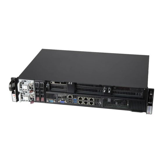
Chapter 1: Introduction 1.2 System Features The following views of the system display the main features. Refer to Appendix B for additional specifications. Front View Handle Dedicated IPMI LAN Port Handle Dual Function Switch COM Port Power Supply GbE RJ45 Ports VGA Port 10G RJ45 Ports Control Panel... - Page 10 Chapter 1: Introduction Logical Storage Drive Numbers Item Description 2.5" SATA3 storage drive bays (logical drive numbers shown) Expansion Slot Locations Item Description Low-profile PCIe 4.0 x16 or two x8 slots PCIe 4.0 x8 slot (slot 2 is disabled if slot 1 is configured as PCIe 4.0 x16) PCIe 4.0 x8 slot (Optional: FH, 10.5"L, CPU SLOT 7, CPU <...
-
Page 11: Control Panel
Chapter 1: Introduction Control Panel Power UID Button/LED BMC Reset Power LED NIC (LAN1) LED NIC (LAN2) LED Information LED Power Fail LED Figure 1-2. Control Panel Control Panel Features Feature Description The main power switch applies or removes primary power from the power supply to the server Power button but maintains standby power. -
Page 12: Rear View
Chapter 1: Introduction Rear View Figure 1-3. System: Rear View System Features: Rear Feature Description Fans Four internal fans... -
Page 13: System Architecture
Chapter 1: Introduction 1.3 System Architecture This section covers the printed circuit board (PCB) locations. PCB Locations Motherboard Figure 1-4. PCB Locations... -
Page 14: Motherboard Layout
Chapter 1: Introduction 1.4 Motherboard Layout Below is a layout of the X12SPM-LN6TF motherboard with jumper, connector and LED locations shown. See the table on the following page for descriptions. For detailed descriptions, pinout information and jumper settings, refer to Chapter 4 or the Motherboard Manual. -
Page 15: Quick Reference Table
Chapter 1: Introduction Quick Reference Table Jumper Description Default Setting JBT1 CMOS Clear Open (Normal) JPL1 LAN3/4/5/6 Enable/Disable Pins 1-2 (Enabled) JPME2 ME Recovery Pins 1-2 (Normal) JPTG1 LAN1/2 (10G Base-T) Enable/Disable Pins 1-2 (Enabled) Description Status LEDM1 BMC Heartbeat LED Blinking Green: BMC Normal LEDPWR Power on LED... - Page 16 Chapter 1: Introduction Connector Description M.2-H M.2 M-Key 2280/22110 Slot (supports PCIe 3.0 x4/SATA3) SLOT4 CPU PCIe 4.0 x16 SLOT6 CPU PCIe 4.0 x16 SLOT7 CPU PCIe 4.0 x8 S-SATA0, S-SATA1 SATA 3.0 Ports with SATA DOM Power S-SGPIO1 Serial Link General Purpose I/O Connection Header TPM1/PORT80 Trusted Platform Module (TPM)/Port 80 Connector USB0/1...
-
Page 17: Motherboard Block Diagram
Chapter 1: Introduction Motherboard Block Diagram DIMMG1 DIMMC1 DIMMH1 DIMMD1 DIMME1 DIMMA1 DIMMF1 DIMMB1 PCI-E X16-Gen4 JPCIE4 PE2[0:15] PCI-E X4-Gen4 RJ45 PE0[0:3] Rear I/O intel PCI-E X16-Gen4 10G *2 NCSI JPCIE6 X550-AT2 PE1[0:15] PCI-E X8-Gen4 JPCIE7 PE0[8:15] PCI-E X4-Gen4 intel RJ45 Rear I/O PE0[4:7]... -
Page 18: Chapter 2 Server Installation
Chapter 2: Server Installation Chapter 2 Server Installation 2.1 Overview This chapter provides advice and instructions for mounting your system in a server rack. If your system is not already fully integrated with system memory etc., refer to Chapter 3 for details on installing those specific components. -
Page 19: Server Precautions
Chapter 2: Server Installation • Always make sure the rack is stable before extending a server or other component from the rack. • You should extend only one server or component at a time - extending two or more simul- taneously may cause the rack to become unstable. -
Page 20: Mechanical Loading
Chapter 2: Server Installation Mechanical Loading Equipment should be mounted into a rack so that a hazardous condition does not arise due to uneven mechanical loading. Circuit Overloading Consideration should be given to the connection of the equipment to the power supply circuitry and the effect that any possible overloading of circuits might have on overcurrent protection and power supply wiring. -
Page 21: Identifying The Sections Of The Rack Rails
Chapter 2: Server Installation 2.3 Identifying the Sections of the Rack Rails The chassis package includes the outer rack rail assemblies in the rack mounting kit. The inner rails are pre-installed onto the chassis. Inner Rails (Inner rail is preinstalled on the chassis) Inner Rail Locking Tabs Figure 2-1. -
Page 22: Inner Rails
Chapter 2: Server Installation Inner Rails The inner rails are pre-attached to the chassis, but should the need arise to remove them, reinstallation of the rails is simple and can be accomplished with a screwdriver. Installing the Inner Rails 1. Place the inner rail on the side of the chassis aligning the hooks of the chassis with the inner rail holes. -
Page 23: Installing The Outer Rails Onto The Rack
Chapter 2: Server Installation Installing the Outer Rails onto the Rack Outer rails attach to the rack and hold the server in place. The outer rails for the chassis extend between 30 inches and 33 inches. Installing the Outer Rails to the Rack 1. - Page 24 Chapter 2: Server Installation 2. Press upward on the locking tab at the rear end of the middle rail. 3. Push the middle rail back into the outer rail. 4. Hang the hooks on the front of the outer rail onto the square holes on the front of the rack.
-
Page 25: Installing The Chassis Into The Rack
Chapter 2: Server Installation 2.4 Installing the Chassis into the Rack 1. Confirm that the chassis includes the inner rails and rail extensions. Also, confirm that the outer rails are installed on the rack. 2. Align the chassis rails with the front of the rack rails. 3. -
Page 26: Chapter 3 Maintenance And Component Installation
Chapter 3: Maintenance and Component Installation Chapter 3 Maintenance and Component Installation This chapter provides instructions on installing and replacing main system components. To prevent compatibility issues, only use components that match the specifications and/or part numbers given. Installation or replacement of most components require that power first be removed from the system. -
Page 27: Accessing The Chassis
Chapter 3: Maintenance and Component Installation 3.2 Accessing the Chassis The top cover is removable to access the chassis components. Removing the Top Cover 1. Remove two screws and slide the cover back and off. Caution: Except for short periods of time, do not operate the server without the cover in place. The chassis cover must be in place to allow for proper airflow and to prevent overheating. -
Page 28: Processor And Heatsink
3. Check that the plastic protective cover is on the CPU socket and that none of the socket pins are bent. If they are, contact your retailer. 4. Refer to the Supermicro website for updates on processor and memory support. Note: All graphics in this manual are for illustration only. Your components may look different. -
Page 29: Overview Of The Processor Carrier Assembly
Chapter 3: Maintenance and Component Installation Overview of the Processor Carrier Assembly The processor carrier assembly contains the Intel Xeon Scalable Family 3rd Gen/4th Gen Series and a processor carrier. 1. Processor 2. Processor Carrier Overview of the CPU Socket The CPU socket is protected by a plastic protective cover. -
Page 30: Overview Of The Processor Heatsink Module
Chapter 3: Maintenance and Component Installation Overview of the Processor Heatsink Module The Processor Heatsink Module (PHM) contains a heatsink, a processor carrier, and the. 1. Heatsink with Thermal Grease 2. Processor Carrier 3. Processor Processor Heatsink Module... -
Page 31: Creating The 3Rd Generation Intel® Xeon® Scalable Processors Carrier Assembly
CPU Pin 1 Processor Carrier Assembly Note: The following CPU carriers have been successfully tested in our labs and are available from Supermicro. Please order the CPU carriers with the CPU heatsink. SKT-1205L-P4IC-FXC Intel 3rd Generation Xeon Scalable Processors... -
Page 32: Assembling The Processor Heatsink Module
Chapter 3: Maintenance and Component Installation Assembling the Processor Processor Carrier Assembly Heatsink Module (Upside Down) After creating the processor carrier assembly for the processor, mount it onto the heatsink to create the processor heatsink module (PHM): 1. Note the label on top of the heatsink, which marks the heatsink mounting holes as 1, 2, 3, and 4. -
Page 33: Preparing The Cpu Socket For Installation
Chapter 3: Maintenance and Component Installation Preparing the CPU Socket for Installation This motherboard comes with a plastic protective cover installed on the CPU socket. Remove it from the socket to install the Processor Heatsink Module (PHM). Gently pull up one corner of the plastic protective cover to remove it. -
Page 34: Installing The Processor Heatsink Module
Chapter 3: Maintenance and Component Installation Installing the Processor Heatsink Module After assembling the Processor Heatsink Module (PHM), install it onto the CPU socket: 1. Align hole 1 of the heatsink with the printed triangle on the CPU socket. See the left image below. -
Page 35: Removing The Processor Heatsink Module
Chapter 3: Maintenance and Component Installation Removing the Processor Heatsink Module Before removing the processor heatsink module Remove the screws in the sequence of 4, 3, 2, 1 (PHM) from the motherboard, shut down the system and then unplug the AC power cord from all power supplies. -
Page 36: Memory
Chapter 3: Maintenance and Component Installation 3.4 Memory The X12SPM-LN6TF supports up to 2048GB of ECC RDIMM/LRDIMM/LRDIMM 3DS with speeds of up to 3200MHz in eight slots. Refer to the tables below for the recommended DIMM population order and additional memory information. 1 CPU, 8-DIMM Slots Number of DIMMs Memory Population Sequence... - Page 37 Chapter 3: Maintenance and Component Installation UID_LED1 JUIDB1 JLANLED1 JLANLED2 SRW1 SRW1 JIPMB1 USB6/7 (3.0) JVRM2 AST2600 USB0/1 LEDM1 JVRM1 LAN5/6 LAN3/4 IPMI_LAN COM1 LAN1/2 JNVI2C1 SRW2 X12SPM-LN4F/-TF/LN6TF REV: 2.00 DESIGNED IN USA M.2-H PCI-E 3.0X4/S-SATA2 JPWR1 JBT1 JPH1 S-SGPIO1 621A BAR CODE MAC CODE...
-
Page 38: Dimm Installation
Chapter 3: Maintenance and Component Installation DIMM Installation UID_LED1 JUIDB1 JLANLED1 JLANLED2 JIPMB1 SRW1 SRW1 1. Insert the desired number of DIMM modules USB6/7 (3.0) JVRM2 AST2600 USB0/1 LEDM1 JVRM1 LAN5/6 LAN3/4 IPMI_LAN COM1 based on the recommended DIMM population LAN1/2 JNVI2C1 SRW2... -
Page 39: Motherboard Battery
Chapter 3: Maintenance and Component Installation 3.5 Motherboard Battery The motherboard uses non-volatile memory to retain system information when system power is removed. This memory is powered by a lithium battery residing on the motherboard. Replacing the Battery Begin by the removing the top cover from the system. 1. -
Page 40: Chassis Components
The CSE-211M-R000NDP chassis supports up to two 2.5" storage drives in drive carriers to simplify their removal from the chassis. These carriers also help promote proper airflow. Note: Enterprise level hard disk drives are recommended for use in Supermicro chassis and servers. For information on recommended HDDs, visit the Supermicro website at http://www. -
Page 41: Installing Drives
Chapter 3: Maintenance and Component Installation Installing Drives Removing Drive Carriers from the Chassis 1. Push the release button on the drive carrier. This releases and extends the drive carrier handle. 2. Swing the handle fully out. 3. Grasp the handle and use it to pull the drive carrier out of its bay. Caution: Except for short periods of time (swapping drives), do not operate the server with the drive carriers removed from the bays, regardless of how many drives are installed, for proper airflow. - Page 42 Chapter 3: Maintenance and Component Installation Installing a 2.5" Hard Drive 1. Place the hard drive carrier on a flat surface. 2. The physical size of the drive does not permit using the stubs to hold the right side of the drive.
-
Page 43: Installing A Pci Expansion Card
Chapter 3: Maintenance and Component Installation Installing a PCI Expansion Card Two PCIe expansion cards can be installed into the system. Installing a Riser Card 1. Power down the system and remove the cover. 2. Remove the screw as shown below. Figure 3-6. - Page 44 Chapter 3: Maintenance and Component Installation Figure 3-7. PCIe Slots and Cable Connectors Cables for PCIe Slots SlimSAS Cable Connection PCIe Slot 1 PCIe Slot 2 JPCIE1A1 and JPCIE1B1 PCIe 4.0 x16 JPCIE1A1 and JPCIE2A1 PCIe 4.0 x8 PCIe 4.0 x8...
-
Page 45: Installing A Pci Expansion Card
Chapter 3: Maintenance and Component Installation Installing a PCI Expansion Card The system includes slots for PCI expansion cards. Riser cards position the expansion cards at a 90 degree angle, allowing them to fit inside the 1U chassis. Slot 7 accommodates one x8 and one x16 FHHL card. - Page 46 Chapter 3: Maintenance and Component Installation 3. Remove the bracket from the chassis using the square hole at the top of the bracket. 4. Install the entire assembly into the appropriate slot on the serverboard while aligning the bracket with the front of the chassis. 5.
-
Page 47: Installing A Pci Expansion Card
Chapter 3: Maintenance and Component Installation Installing a PCI Expansion Card Both slots 4 and 6 can accommodate x16 FHHL cards. Installing PCI Expansion Cards 1. Remove the top cover, if necessary. 2. Remove the card bracket from the chassis by unscrewing the screw holding the bracket indicated in the figure below. - Page 48 Chapter 3: Maintenance and Component Installation Figure 3-11. PCIe Slots...
-
Page 49: System Cooling
Chapter 3: Maintenance and Component Installation 3.7 System Cooling Fans Four internal fans provide cooling. Changing a System Fan 1. Determine which fan is failing. If possible, use IPMI. If not, remove the chassis cover while the power is on, and examine the fans to determine which one has failed. 2. -
Page 50: Air Shroud
Chapter 3: Maintenance and Component Installation Air Shroud The system requires air shrouds for each node to maximize airflow efficiency. Installing the Air Shroud Before installing/removing the air shroud, please remove all riser card brackets first. Place the air shroud as shown below. Figure 3-13. -
Page 51: Power Supply
The power supplies are auto-switching capable. The power supplies can operate at a -44Vdc to -65Vdc input range. If replacing a power supply, the system does not need to be powered down. New units can be ordered directly from Supermicro or authorized distributors. - Page 52 Chapter 3: Maintenance and Component Installation Release Button Figure 3-15. Removing the Power Supply...
-
Page 53: Bmc Reset
Chapter 3: Maintenance and Component Installation 3.9 BMC Reset The BMC can be reset using the button on the front control panel or on the chassis rear. • Reset – Press and hold the button. After six seconds, the LED blinks at 2Hz. The BMC resets and the reset duration is ~250 ms. -
Page 54: Chapter 4 Motherboard Connections
Chapter 4: Motherboard Connections Chapter 4 Motherboard Connections This section describes the connections on the motherboard and provides pinout definitions. Note that depending on how the system is configured, not all connections are required. The LEDs on the motherboard are also described here. A motherboard layout indicating component locations may be found in Chapter 1. - Page 55 Chapter 4: Motherboard Connections 8-Pin Power Connector JPV1 is an 8-pin 12V DC power input for the CPU that must be connected to the power supply. Refer to the table below for pin definitions. 8-pin Power Pin Definitions Pin# Definition 1 - 4 Ground 5 - 8...
- Page 56 Chapter 4: Motherboard Connections Fan Headers There are five 4-pin fan headers (FAN1 ~ FAN4, FANA) on the motherboard. All these 4-pin fan headers are backwards compatible with the traditional 3-pin fans. However, fan speed control is available for 4-pin fans only by Thermal Management via the IPMI 2.0 interface. Refer to the table below for pin definitions.
- Page 57 Port 80 connection. Use this header to enhance system performance and data security. Refer to the table below for pin definitions. Please go to the following link for more information on the TPM: http://www.supermicro.com/manuals/other/TPM.pdf. Trusted Platform Module Header Pin Definitions...
- Page 58 Chapter 4: Motherboard Connections NVMe I C Header Connector JNVI C1 is a management header for the Supermicro AOC NVMe PCIe peripheral cards. Please connect the I C cable to this connector. NVMe I2C Header Pin Definitions Pin# Definition Data Clock +3.3V...
- Page 59 Parallel ATA. Refer to the tables below for pin definitions. Note: For more information on the SATA HostRAID configuration, please refer to the Intel SATA HostRAID user's guide posted on our website at http://www.supermicro.com. SATA 3.0 Ports Pin Definitions...
-
Page 60: Control Panel
JF1 contains header pins for various buttons and indicators that are normally located on a control panel at the front of the chassis. These connectors are designed specifically for use with Supermicro chassis. See the figure below for the descriptions of the front control panel buttons and LED indicators. - Page 61 Chapter 4: Motherboard Connections Power Fail LED The Power Fail LED connection is located on pins 5 and 6 of JF1. Refer to the table below for pin definitions. Power Fail LED Pin Definitions (JF1) Pin# Definition 3.3V PWR Supply Fail Overheat (OH)/Fan Fail Connect an LED cable to pins 7 and 8 of the Front Control Panel to use the Overheat/Fan Fail LED connections.
- Page 62 Chapter 4: Motherboard Connections Power LED The Power LED connection is located on pins 15 and 16 of JF1. Refer to the table below for pin definitions. Power LED Pin Definitions (JF1) Pins Definition 3.3V Stby PWR LED NMI Button The non-maskable interrupt (NMI) button header is located on pins 19 and 20 of JF1.
-
Page 63: Headers And Connectors
Chapter 4: Motherboard Connections 4.2 Headers and Connectors Fan Headers There are four 4-pin fan headers on the motherboard: two (FAN3~FAN4) on the front plane (see locations below), and two (FAN1~FAN2) on the HDD backplane. All these 4-pin fan headers are backwards compatible with the traditional 3-pin fans. However, fan speed control is available for 4-pin fans only by Thermal Management via the BMC interface. - Page 64 The JTPM1 header is used to connect a Trusted Platform Module (TPM)/Port 80, which is available from Supermicro (optional). A TPM/Port 80 connector is a security device that supports encryption and authentication in hard drives. It allows the motherboard to deny access if the TPM associated with the hard drive is not installed in the system.
-
Page 65: Input/Output Ports
Chapter 4: Motherboard Connections 4.3 Input/Output Ports See the figure below for the locations and descriptions of the I/O ports on the rear of the motherboard. Figure 4-1. I/O Port Locations and Definitions Rear I/O Ports Description Description VGA Port LAN1 (10G on -LN6TF) Dedicated IPMI LAN LAN4... - Page 66 Chapter 4: Motherboard Connections Universal Serial Bus (USB) Ports There are two USB 2.0 ports (USB0/1) and two USB 3.2 Gen 1 ports (USB6/7) located on the I/O back panel. The motherboard also has two front access USB 2.0 headers (USB2/3 and USB4/5) and one front access USB 3.2 Gen 1 header (USB8/9).
- Page 67 Chapter 4: Motherboard Connections Unit Identifier Switch (UID-SW): One button with two functions A Unit Identifier (UID) switch and two LED Indicators are located on the motherboard. The UID switch, UID-SW, is located next to the VGA port on the back panel. Function User Input Behavior...
-
Page 68: Jumpers
Chapter 4: Motherboard Connections 4.4 Jumpers How Jumpers Work To modify the operation of the motherboard, jumpers can be used to choose between optional settings. Jumpers create shorts between two pins to change the function of the connector. Pin 1 is identified with a square solder pad on the printed circuit board. Refer to the diagram below for an example of jumping pins 1 and 2. - Page 69 Chapter 4: Motherboard Connections 1GbE LAN Enable/Disable JPL1 allows you to enable or disable the 1GbE LAN for the -LN4F and -LN6TF motherboards. The default setting is Enabled. 1GbE LAN Enable/Disable Jumper Settings Jumper Setting Definition Pins 1-2 Enable Pins 2-3 Disable 10GbE LAN Enable/Disable JTPG1 allows you to enable or disable the 10GbE LAN ports on the -TF and -LN6TF...
-
Page 70: Led Indicators
Chapter 4: Motherboard Connections 4.5 LED Indicators LAN LEDs Six LAN ports (LAN1~6) are located on the back I/O panel of the motherboard. Each Ethernet LAN port has two LEDs. The yellow LED indicates activity, while the other Link LED may be green, amber, or off to indicate the speed of the connection. - Page 71 Chapter 4: Motherboard Connections Onboard Power LED The Onboard Power LED is located at LEDPWR on the motherboard. When this LED is on, the system is on. Be sure to turn off the system and unplug the power cord before removing or installing components.
-
Page 72: Chapter 5 Software
USB/SATA DVD drive, or a USB flash drive, or the BMC KVM console. 2. Retrieve the proper RST/RSTe driver. Go to the Supermicro web page for your motherboard and click on "Download the Latest Drivers and Utilities", select the proper driver, and copy it to a USB flash drive. - Page 73 Chapter 5: Software 4. During Windows Setup, continue to the dialog where you select the drives on which to install Windows. If the disk you want to use is not listed, click on “Load driver” link at the bottom left corner. Figure 5-2.
-
Page 74: Driver Installation
The Supermicro website contains drivers and utilities for your system at https://www. supermicro.com/wdl/driver. Some of these must be installed, such as the chipset driver. After accessing the website, go into the CDR_Images (in the parent directory of the above link) and locate the ISO file for your motherboard. Download this file to a USB flash drive or a DVD. -
Page 75: Superdoctor ® 5
5.3 SuperDoctor ® The Supermicro SuperDoctor 5 is a program that functions in a command-line or web-based interface for Windows and Linux operating systems. The program monitors such system health information as CPU temperature, system voltages, system power consumption, fan speed, and provides alerts via email or Simple Network Management Protocol (SNMP). -
Page 76: Bmc
There are several BIOS settings that are related to BMC. For general documentation and information on BMC, visit our website at: www.supermicro.com/en/solutions/management-software/bmc-resources BMC ADMIN User Password For security, each system is assigned a unique default BMC password for the ADMIN user. -
Page 77: Chapter 6 Optional Components
Chapter 6: Optional Components Chapter 6 Optional Components This chapter describes optional system components and installation procedures. 6.1 Optional Parts List Optional Parts List Description Part Number Quantity... -
Page 78: Chapter 7 Troubleshooting And Support
Chapter 7 Troubleshooting and Support 7.1 Information Resources Website A great deal of information is available on the Supermicro website, supermicro.com. Menu Icon Figure 7-1. Supermicro Website • Specifications for servers and other hardware are available by clicking the menu icon, then selecting the Products option. -
Page 79: Baseboard Management Controller (Bmc)
Security Center for recent security notices Supermicro Phone and Addresses 7.2 Baseboard Management Controller (BMC) The system supports the Baseboard Management Controller (BMC). BMC is used to provide remote access, monitoring and management. There are several BIOS settings that are related to BMC. -
Page 80: Troubleshooting Procedures
Chapter 7: Troubleshooting and Support 7.3 Troubleshooting Procedures Use the following procedures to troubleshoot your system. If you have followed all of the procedures below and still need assistance, refer to the Technical Support Procedures Returning Merchandise for Service section(s) in this chapter. Power down the system before changing any non hot-swap hardware components. -
Page 81: System Boot Failure
Chapter 7: Troubleshooting and Support 3. Make sure that no short circuits exist between the motherboard and chassis. 4. Disconnect all cables from the motherboard, including those for the keyboard and mouse. 5. Remove all add-on cards. 6. Install a CPU, a heatsink, connect the internal speaker (if applicable), and the power LED to the motherboard. -
Page 82: When The System Becomes Unstable
2. Memory support: Make sure that the memory modules are supported by testing the modules using memtest86 or a similar utility. Note: Refer to the product page on our website at http://www.supermicro.com for memory and CPU support and updates. 3. HDD support: Make sure that all hard disk drives (HDDs) work properly. Replace the bad HDDs with good ones. - Page 83 Chapter 7: Troubleshooting and Support 5. Check and change one component at a time instead of changing several items at the same time. This will help isolate and identify the problem. 6. To find out if a component is good, swap this component with a new one to see if the system will work properly.
-
Page 84: Crash Dump Using Bmc
In the event of a processor internal error (IERR) that crashes your system, you may want to provide information to support staff. You can download a crash dump of status information using BMC. The BMC manual is available at https://www.supermicro.com/en/solutions/ management-software/bmc-resources. Check BMC Error Log 1. -
Page 85: Uefi Bios Recovery
Warning: Do not upgrade the BIOS unless your system has a BIOS-related issue. Flashing the wrong BIOS can cause irreparable damage to the system. In no event shall Supermicro be liable for direct, indirect, special, incidental, or consequential damages arising from a BIOS update. - Page 86 USB device or a writable CD/DVD. Note 1: If you cannot locate the "Super.ROM" file in your drive disk, visit our website at www.supermicro.com to download the BIOS package. Extract the BIOS binary image into a USB flash device and rename it "Super.ROM" for the BIOS recovery use.
- Page 87 Chapter 7: Troubleshooting and Support Note: At this point, you may decide if you want to start the BIOS recovery. If you decide to proceed with BIOS recovery, follow the procedures below. 4. When the screen as shown above displays, use the arrow keys to select the item "Proceed with flash update"...
- Page 88 Chapter 7: Troubleshooting and Support 7. Press <Del> continuously during system boot to enter the BIOS Setup utility. From the top of the tool bar, select Boot to enter the submenu. From the submenu list, select Boot Option #1 as shown below. Then, set Boot Option #1 to [UEFI AP:UEFI: Built-in EFI Shell]. Press <F4>...
- Page 89 Chapter 7: Troubleshooting and Support Note: Do not interrupt this process until the BIOS flashing is complete. 9. The screen above indicates that the BIOS update process is complete. When you see the screen above, unplug the AC power cable from the power supply, clear CMOS, and plug the AC power cable in the power supply again to power on the system.
-
Page 90: Cmos Clear
Chapter 7: Troubleshooting and Support 7.6 CMOS Clear JBT1 is used to clear CMOS, which will also clear any passwords. Instead of pins, this jumper consists of contact pads to prevent accidentally clearing the contents of CMOS. To Clear CMOS 1. -
Page 91: Where To Get Replacement Components
7.7 Where to Get Replacement Components If you need replacement parts for your system, to ensure the highest level of professional service and technical support, purchase exclusively from our Supermicro Authorized Distributors/System Integrators/Resellers. A list can be found at: http://www.supermicro.com. -
Page 92: Vendor Support Filing System
For issues related to Red Hat Enterprise Linux, since it is a subscription based OS, contact your account representative. 7.9 Feedback Supermicro values your feedback as we strive to improve our customer experience in all facets of our business. Please email us at techwriterteam@supermicro.com to provide feedback on our manuals. -
Page 93: Appendix A Standardized Warning Statements For Ac/Dc Systems
Supermicro's Technical Support department for assistance. Only certified technicians should attempt to install or configure components. Read this appendix in its entirety before installing or configuring components in the Supermicro chassis. These warnings may also be found on our website at http://www.supermicro.com/about/... - Page 94 Appendix A: Warning Statements Warnung WICHTIGE SICHERHEITSHINWEISE Dieses Warnsymbol bedeutet Gefahr. Sie befinden sich in einer Situation, die zu Verletzungen führen kann. Machen Sie sich vor der Arbeit mit Geräten mit den Gefahren elektrischer Schaltungen und den üblichen Verfahren zur Vorbeugung vor Unfällen vertraut. Suchen Sie mit der am Ende jeder Warnung angegebenen Anweisungsnummer nach der jeweiligen Übersetzung in den übersetzten Sicherheitshinweisen, die zusammen mit diesem Gerät ausgeliefert wurden.
- Page 95 Appendix A: Warning Statements . ٌ ا ك ً ف حالة و ٌ يك أى تتسبب ف اصابة جسذ ة ٌ هذا الزهز ع ٌ خطز !تحذ ز قبل أى تعول عىل أي هعذات،يك عىل علن بالوخاطز ال ا ٌجوة عي الذوائز ٍ...
- Page 96 Appendix A: Warning Statements Warnung Vor dem Anschließen des Systems an die Stromquelle die Installationsanweisungen lesen. ¡Advertencia! Lea las instrucciones de instalación antes de conectar el sistema a la red de alimentación. Attention Avant de brancher le système sur la source d'alimentation, consulter les directives d'installation. .יש...
- Page 97 Appendix A: Warning Statements Warnung Dieses Produkt ist darauf angewiesen, dass im Gebäude ein Kurzschluss- bzw. Überstromschutz installiert ist. Stellen Sie sicher, dass der Nennwert der Schutzvorrichtung nicht mehr als: 250 V, 20 A beträgt. ¡Advertencia! Este equipo utiliza el sistema de protección contra cortocircuitos (o sobrecorrientes) del edificio.
- Page 98 Appendix A: Warning Statements 電源切断の警告 システムコンポーネントの取り付けまたは取り外しのために、 シャーシー内部にアクセスするには、 システムの電源はすべてのソースから切断され、 電源コードは電源モジュールから取り外す必要が あります。 警告 在你打开机箱并安装或移除内部器件前,必须将系统完全断电,并移除电源线。 警告 在您打開機殼安裝或移除內部元件前,必須將系統完全斷電,並移除電源線 。 Warnung Das System muss von allen Quellen der Energie und vom Netzanschlusskabel getrennt sein, das von den Spg.Versorgungsteilmodulen entfernt wird, bevor es auf den Chassisinnenraum zurückgreift, um Systemsbestandteile anzubringen oder zu entfernen.
- Page 99 Appendix A: Warning Statements يجب فصم اننظاو من جميع مصادر انطاقت وإ ز انت سهك انكهرباء من وحدة امداد انطاقت قبم انىصىل إىن امنناطق انداخهيت نههيكم نتثبيج أو إ ز انت مكىناث الجهاز 경고! 시스템에 부품들을 장착하거나 제거하기 위해서는 섀시 내부에 접근하기 전에 반드시 전원 공급장치로부터...
- Page 100 Appendix A: Warning Statements Attention Il est vivement recommandé de confier l'installation, le remplacement et la maintenance de ces équipements à des personnels qualifiés et expérimentés. !אזהרה .צוות מוסמך בלבד רשאי להתקין, להחליף את הציוד או לתת שירות עבור הציוד واملدربيه...
- Page 101 Appendix A: Warning Statements Warnung Diese Einheit ist zur Installation in Bereichen mit beschränktem Zutritt vorgesehen. Der Zutritt zu derartigen Bereichen ist nur mit einem Spezialwerkzeug, Schloss und Schlüssel oder einer sonstigen Sicherheitsvorkehrung möglich. ¡Advertencia! Esta unidad ha sido diseñada para instalación en áreas de acceso restringido. Sólo puede obtenerse acceso a una de estas áreas mediante la utilización de una herramienta especial, cerradura con llave u otro medio de seguridad.
- Page 102 Appendix A: Warning Statements Battery Handling Warning! There is the danger of explosion if the battery is replaced incorrectly. Replace the battery only with the same or equivalent type recommended by the manufacturer. Dispose of used batteries according to the manufacturer's instructions 電池の取り扱い...
- Page 103 Appendix A: Warning Statements هناك خطر من انفجار يف حالة اسحبذال البطارية بطريقة غري صحيحة فعليل اسحبذال البطارية فقط بنفس النىع أو ما يعادلها مام أوصث به الرشمة املصنعة جخلص من البطاريات املسحعملة وفقا لحعليامت الرشمة الصانعة 경고! 배터리가 올바르게 교체되지 않으면 폭발의 위험이 있습니다. 기존 배터리와 동일하거나 제 조사에서...
- Page 104 Appendix A: Warning Statements ¡Advertencia! Puede que esta unidad tenga más de una conexión para fuentes de alimentación. Para cortar por completo el suministro de energía, deben desconectarse todas las conexiones. Attention Cette unité peut avoir plus d'une connexion d'alimentation. Pour supprimer toute tension et tout courant électrique de l'unité, toutes les connexions d'alimentation doivent être débranchées.
- Page 105 Appendix A: Warning Statements Backplane Voltage Warning! Hazardous voltage or energy is present on the backplane when the system is operating. Use caution when servicing. バックプレーンの電圧 システムの稼働中は危険な電圧または電力が、 バックプレーン上にかかっています。 修理する際には注意く ださい。 警告 当系统正在进行时,背板上有很危险的电压或能量,进行维修时务必小心。 警告 當系統正在進行時,背板上有危險的電壓或能量,進行維修時務必小心 。 Warnung Wenn das System in Betrieb ist, treten auf der Rückwandplatine gefährliche Spannungen oder Energien auf.
- Page 106 Appendix A: Warning Statements هناك خطز مه التيار الكهزبايئ أوالطاقة املىجىدة عىل اللىحة عندما يكىن النظام يعمل كه حذ ر ا عند خدمة هذا الجهاس 경고! 시스템이 동작 중일 때 후면판 (Backplane)에는 위험한 전압이나 에너지가 발생 합니다. 서비스 작업 시 주의하십시오. Waarschuwing Een gevaarlijke spanning of energie is aanwezig op de backplane wanneer het systeem in gebruik is.
- Page 107 Appendix A: Warning Statements תיאום חוקי החשמל הארצי !אזהרה .התקנת הציוד חייבת להיות תואמת לחוקי החשמל המקומיים והארציים تركيب املعدات الكهربائية يجب أن ميتثل للقىاويه املحلية والىطىية املتعلقة بالكهرباء 경고! 현 지역 및 국가의 전기 규정에 따라 장비를 설치해야 합니다. Waarschuwing Bij installatie van de apparatuur moet worden voldaan aan de lokale en nationale elektriciteitsvoorschriften.
- Page 108 Appendix A: Warning Statements Attention La mise au rebut ou le recyclage de ce produit sont généralement soumis à des lois et/ou directives de respect de l'environnement. Renseignez-vous auprès de l'organisme compétent. סילוק המוצר !אזהרה .סילוק סופי של מוצר זה חייב להיות בהתאם להנחיות וחוקי המדינה التخلص...
- Page 109 Appendix A: Warning Statements Warnung Gefährlich Bewegende Teile. Von den bewegenden Lüfterblätter fern halten. Die Lüfter drehen sich u. U. noch, wenn die Lüfterbaugruppe aus dem Chassis genommen wird. Halten Sie Finger, Schraubendreher und andere Gegenstände von den Öffnungen des Lüftergehäuses entfernt.
- Page 110 Verbindungskabeln, Stromkabeln und/oder Adapater, die Ihre örtlichen Sicherheitsstandards einhalten. Der Gebrauch von anderen Kabeln und Adapter können Fehlfunktionen oder Feuer verursachen. Die Richtlinien untersagen das Nutzen von UL oder CAS zertifizierten Kabeln (mit UL/CSA gekennzeichnet), an Geräten oder Produkten die nicht mit Supermicro gekennzeichnet sind.
- Page 111 حجم املوصل والقابس السليم. استخدام أي كابالت ومحوالت أخرى قد يتسبب يف عطل أو حريق. يحظر قانون السالمة لألجهزة الكهربائية واملعدات استخدام الكابالت املعتمدة من قبلUL أوCSA ( والتي تحمل عالمةUL/CSA) مع أي معدات أخرى غري املنتجات املعنية واملحددة من قبلSupermicro.
- Page 112 사항을 준수하여 제공되거나 지정된 연결 혹은 구매 케이블, 전원 케이블 및 AC 어댑터를 사용하십시오. 다른 케이블이나 어댑터를 사용하면 오작동이나 화재가 발생할 수 있습니다. 전기 용품 안전법은 UL 또는 CSA 인증 케이블 (코드에 UL / CSA가 표시된 케이블)을 Supermicro 가 지정한 제품 이외의 전기 장치에 사용하는 것을 금지합니다. Stroomkabel en AC-Adapter...
- Page 113 Appendix A: Warning Statements Warnung Wenn Litzenverdrahtung erforderlich ist, sind zugelassene Verdrahtungsabschlüsse, z.B. für einen geschlossenen Regelkreis oder gabelförmig, mit nach oben gerichteten Kabelschuhen zu verwenden. Diese Abschlüsse sollten die angemessene Größe für die Drähte haben und sowohl die Isolierung als auch den Leiter festklemmen. ¡Advertencia! Cuando se necesite hilo trenzado, utilizar terminales para cables homologados, tales como las de tipo "bucle cerrado"...
- Page 114 Appendix A: Warning Statements Waarschuwing Wanneer geslagen bedrading vereist is, dient u bedrading te gebruiken die voorzien is van goedgekeurde aansluitingspunten, zoals het gesloten-lus type of het grijperschop type waarbij de aansluitpunten omhoog wijzen. Deze aansluitpunten dienen de juiste maat voor de draden te hebben en dienen zowel de isolatie als de geleider vast te klemmen.
- Page 115 Appendix A: Warning Statements وأ ةقلغم ةقلح لثم ،اهيلع ةقفاوملا ءاهنإ كالسألا مادختساو ،لبسلا مهب تعطقت نيذلا كالسألا ابولطم نوكي امدنع بجيو كالسألل بسانملا مجحلا نوكي تاءاهنإلا هذهل يغبنيو .ةبولقم تاورعلا عم عونلا ةيقيقحلا اهئامسأب ءايشألا .لصومو لزعلا نم لك حبك 주의! 다음...
- Page 116 Appendix A: Warning Statements Warnung In mit Gleichstrom betriebenen Terminals kann es zu gefählicher Spannung kommen. Die Terminals müssen abgedeckt werden, wenn sie nicht in Betrieb sind. Stellen Sie bei Benutzung der Abdeckung sicher, dass alle nicht isolierten, stromführenden Kabel abgedeckt sind. ¡Advertencia! Puede haber energía o voltaje peligrosos en los terminales eléctricos de CC.
-
Page 117: Appendix B System Specifications
Appendix B: System Specifications Appendix B System Specifications Processors (per node) Single 3rd Generation Intel® Xeon® Scalable processor (LGA4189) Note: Refer to the motherboard specifications pages on our website for updates to supported processors. Chipset Intel® C621A BIOS 256Mb AMI BIOS SPI Flash BIOS ®... - Page 118 Appendix B: System Specifications Power Supply Model: PWS-x, 600 W redundant module, 80Plus Titanium level AC Input Voltages: 100-240 VAC Rated Input Current: 1800W: 200-220Vac 1980W: 220-230Vac 2090W: 230-240Vac 2090W: 180-220Vac (for UL/cUL only) 2200W: 220-240Vac (for UL/cUL only) 2090W: 230-240Vdc (for CCC only)> Rated Input Frequency: 50-60 Hz Rated Output Power: +12 V Max: 100A / Min: 0A (100-127Vac)
- Page 119 Appendix B: System Specifications Applied Directives, Standards EMC/EMI: 2014/30/EU (EMC Directive) Electromagnetic Compatibility Regulations 2016 FCC Part 15 ICE-003 VCCI-CISPR 32 AS/NZS CISPR 32 BS/EN55032 BS/EN55035 CISPR 24/CISPR 35 BS/EN 61000-3-2 BS/EN 61000-3-3 BS/EN 61000-4-2 BS/EN 61000-4-3 BS/EN 61000-4-4 BS/EN 61000-4-5 BS/EN 61000-4-6 BS/EN 61000-4-8 BS/EN 61000-4-11...
Need help?
Do you have a question about the SuperServer 210P-FRDN6T and is the answer not in the manual?
Questions and answers