
Related Manuals for GeoVision GV-BL8714


Summary of Contents for GeoVision GV-BL8714
- Page 1 GV-IP Camera Quick Start Guide Bullet Camera Target Bullet Camera Before attempting to connect or operate this product, ICH265-BL-EBL-A please read these instructions carefully and save this manual for future use.
- Page 2 GeoVision. Every effort has been made to ensure that the information in this manual is accurate. GeoVision, Inc. makes no expressed or implied warranty of any kind and assumes no responsibility for errors or omissions. No liability is assumed for incidental or consequential damages arising from the use of the information or products contained herein.
- Page 3 Caution Risk of explosion if battery is replaced by an incorrect type. Dispose of used batteries according to the instructions. Safety Notice The GV-IPCAM uses a Lithium battery as the power supply for its internal real-time clock (RTC). The battery should not be replaced unless required! If the battery does need replacing, please observe the following: ...
-
Page 4: Table Of Contents
Contents Caution.................i Safety Notice ...............i Options ................v Creating GV-IP Camera’s Login Credentials....vi Note for Adjusting Focus and Zoom......vii Note for Installing Camera Outdoor......viii Note for Closing the Bullet Camera Cover .....ix ... - Page 5 2.4 Connecting the Camera............34 2.4.1 Wire Definition ............34 2.4.2. Power Connection.............36 Chapter 3 Bullet Camera (Part III)........37 3.1 Packing List ................38 3.2 Overview ................39 3.3 Installation ................40 3.4 Connecting the Camera............43 Chapter 4 Target Bullet Camera (Part I)......45 ...
- Page 6 6.4.1 Wire Definition ............69 6.4.2 Power Connection............69 Chapter 7 Accessing the Camera........70 7.1 System Requirement ..............70 7.2 Accessing the Live View ............70 7.2.1 Checking the Dynamic IP Address ......71 7.2.2 Configuring the IP Address ........72 ...
-
Page 7: Options
Options Optional devices can expand your camera’s capabilities and versatility. Contact your dealer for more information. Device Description The I/O cable is a multi-connector providing I/O, DC 12V power, and audio connectivity for the I/O Cable camera. Length: 106.8 cm (3.5 ft) The GV-Mount Accessories provide a comprehensive lineup of accessories for GV-Mount... -
Page 8: Creating Gv-Ip Camera's Login Credentials
Creating GV-IP Camera’s Login Credentials The default Administrator and Guest accounts are no longer supported by GV-IPCam H.265 series firmware V1.14 or later. When purchasing a new camera or performing factory resetting, you need to set up a login username and password for the camera. Download and install GV-IP Device Utility from the company website. -
Page 9: Note For Adjusting Focus And Zoom
Note for Adjusting Focus and Zoom When adjusting the Focus and Zoom Screws on Bullet Camera, do not over tighten the Focus and Zoom screws. The screws only need to be as tight as your finger can do it. It is not necessary to use any tools to get them tighter. -
Page 10: Note For Installing Camera Outdoor
Note for Installing Camera Outdoor When installing the cameras outdoor, be sure that: The camera is set up above the junction box to prevent water from entering the camera along the cables. Any PoE, power, audio and I/O cables are waterproofed using waterproof silicon rubber or the like. -
Page 11: Note For Closing The Bullet Camera Cover
Note for Closing the Bullet Camera Cover To ensure that the camera performs its full capacity against water and dust, tightly close and lock the camera cover as indicated below. Note for Silica Gel Bags The silica gel bag loses its effectiveness when the dry camera is opened. -
Page 12: Note For Waterproofing Failures
Note for Waterproofing Failures To avoid waterproofing failures, do not open the screw on the camera body. The screw on Ultra Bullet The screw on Target Bullet Camera Camera The screw on GV-EBL2101 / The screw on GV-BL3700 / 2111 / 3101 / 5101 5700... -
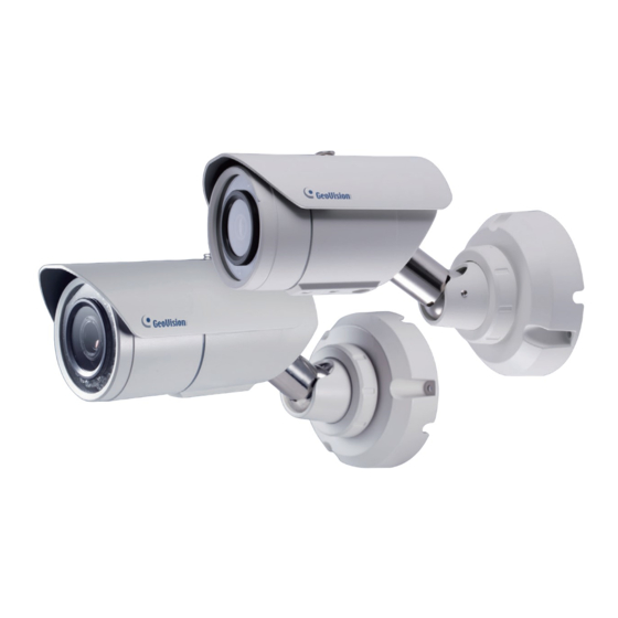
Page 13: Chapter 1 Bullet Camera (Part I)
Bullet Camera (Part I) Chapter 1 Bullet Camera (Part I) The Bullet Cameras are specifically designed for outdoors. They are weatherproof (IP67) and equipped with IR LEDs for infrared illumination in night vision applications. The models described in this chapter use P-Iris, which allows for precise control of exposure in producing images with better clarity and contrast. - Page 14 Model No. Specifications Description 1.3 MP, H.264, P-Iris, f: 3 ~ 9 mm, GV-BL1501 Super Low Lux F/1.2, 1/2.7’’ ø 14 mm Lens 2 MP, H.264, GV-BL2501 Mount Super Low Lux P-Iris, f: 2.8 ~ 12 mm, F/1.7, 1/2.7”, GV-BL2702-3V ø...
- Page 15 Bullet Camera (Part I) Model No. Specifications Description P-Iris, f: 4.5 ~ 9 mm, F/1.2, 1/2.7’’ 5 MP, H.264, 2X GV-BL5311 Optical Zoom ø 14 mm Lens Mount P-Iris, f: 2.8 ~ 12 4 MP, H.265, Motorized mm, F/1.7, 1/2.7”, GV-BL4713 Super Low Lux, varifocal lens...
-
Page 16: Packing List
1.1 Packing List For GV-BL1501 / 2501 / 1511 / 2511 / 5311, refer to the following packing list: Bullet Camera Self Tapping Screw x 3 Plastic Screw Anchor x 3 Torx Wrench x 3 Sun-Shield Cover Kit (Sun-Shield Cover, Philips Head Screw x 2, Plastic Screw Spacer x 2, and Hexagon Screw x 2) ... - Page 17 Bullet Camera (Part I) For GV-BL2702 / 4702 / 4713 / 5713, refer to the following packing list: H.265 Bullet Camera Stand Kit (Conduit Converter, PG21 Conduit Connector, RJ-45 Connector, M3 Screw x 2, Cable Tie) Sun-Shield Cover Kit (Sun-Shield Cover, Philips Head Screws x 2, Plastic Screw Spacers x 2, Hexagon Screws x 2) ...
-
Page 18: Overview
1.2 Overview Twist off the camera cover to access the following: GV-BL4713 / 5713 For GV-BL4713 / 5713, twist off the camera cover and loosen the three screws on the front lid of the sun-shield cover to access the following:... - Page 19 Bullet Camera (Part I) Name Description Receives a micro SD card (SD/SDHC, Memory Card Slot version 2.0 only, Class 10). Zoom Screw Holds the zoom lens in place. Focus Screw Holds the focus lens in place Resets all configurations to factory default. Default Button For details, see 10.
- Page 20 To access the following interface, remove the camera base using the supplied torx wrench. Name Description LAN / PoE Connects to a 10/100 Ethernet or PoE. Audio In Connects a microphone for audio input. Audio Out Connects a speaker for audio output. Connects to I/O devices.
-
Page 21: Installation
Bullet Camera (Part I) 1.3 Installation Follow the steps below to install the Bullet Camera. Paste the supplied sticker to the ceiling/wall. For wall installations, make sure the arrow on the sticker points toward the ceiling. Mount template Drill the shaded area, and insert the screw anchor into the three holes. - Page 22 Loosen the indicated screws and remove the back plate. Align and secure the back plate to the wall/ceiling with the supplied self-tapping screws.
- Page 23 Bullet Camera (Part I) To optionally install a pipe, use one of the two methods illustrated below depending on the type of the back plate that comes with your camera: A. If your plate comes with two knobs as below. Install the supplied conduit converter to the back plate.
- Page 24 Install the Ethernet cable. A. Twist off and remove the cable seal and the conduit connector. Conduit Connector Cable Seal B. Thread an Ethernet cable (with no RJ-45 connector on one end) from the back panel through the cable seal and then through the conduit converter (optionally installed at Step 6A).
- Page 25 Bullet Camera (Part I) Thread wires into the camera. A. Disintegrate the removed conduit connector. You should have 4 parts: B. Remove the terminal block from the supplied power adapter. C. Optionally thread audio wires, adapter wires, and I/O wires through the conduit converter and then through part 1, 2, 3, and 4 of the conduit connector.
- Page 26 For part 2, there are 8 holes each labeled with its diameter. Remove the plugs and push the wires to the corresponding hole listed below: Plug Figure 1-14 2.6 mm: Audio 2 mm: DC12V / AC24V 1.8 mm: DIDO IMPORTANT: ...
- Page 27 Bullet Camera (Part I) Install the base to the back plate on the wall. Connect the wires to the camera. A. Install the terminal blocks to the power adapter and I/O devices. See Power Connection and I/O Device Connections in 1.4 Connecting the Camera.
-
Page 28: Adjusting The Angles
1.3.1 Adjusting the Angles The Bullet Camera is designed to be adjustable in three shafts for easy and flexible installation. First Shaft You can adjust the camera body by 360 degrees to the right or the left. Unscrew the panning lock screw with the torx wrench. Panning Lock Screw Torx Wrench Adjust the angle of camera body to the right or the left, and fasten... - Page 29 Bullet Camera (Part I) Second Shaft You can adjust the camera body up and down by 90, 112.5, 135, 157.5 or 180 degrees by using the gears inside the camera body and the camera base. Unscrew the tilting lock screw with the torx wrench. Tilting Lock Screw Torx Wrench Hold the camera body, and move the camera base to the right to...
- Page 30 Third Shaft You can adjust the camera base by 360°. Unscrew the base fixing screw with the torx wrench. Torx Wrench Base Fixing Screw Adjusting the angle of camera base, and fasten the base fixing screw. 0~360°...
-
Page 31: Adjusting Lens And Inserting A Memory Card
Bullet Camera (Part I) 1.3.2 Adjusting Lens and Inserting a Memory Card To adjust the camera’s zoom and focus or to insert a micro SD card (SD/SDHC, version 2.0 only, Class 10), follow the steps below. Loosen the camera’s cover. Camera’... - Page 32 Loosen the fixing screw. Fixing Screw Slightly pull out the camera module. Insert a micro SD card into the memory card slot. Memory Card Slot Push the camera back and fasten the fixing screw. Insert a new silica gel bag to the camera module and fasten the camera’s cover.
-
Page 33: Installing The Sun-Shield Cover
Bullet Camera (Part I) 1.3.3 Installing the Sun-Shield Cover After setting up the Bullet Camera, now you can install the sun-shield cover to the camera. Fasten the hexagon screws either on top or below the camera. Hexagon Screws Put the sun-shield cover on top of hexagon screws. Make sure to aim the rear hexagon screw at the edge of the sun-shield cover’s aperture for optimal sun-shield performance. -
Page 34: Connecting The Camera
1.4 Connecting the Camera Power Connection Use one of the following methods to supply power to the camera. Use a Power over Ethernet (PoE) adapter to connect the camera to the network, and the power will be provided at the same time. ... - Page 35 Bullet Camera (Part I) I/O Cable (Optional) For GV-BL2702 / 4702 / 4713 / 5713, you can optionally purchase an I/O cable for convenient connection. Wire Definition 2-pin Terminal Block DC 12V Pink RCA Audio Input Green RCA Audio Output Digital Output Digital I/O Black...
-
Page 36: Chapter 2 Bullet Camera (Part Ii)
Chapter 2 Bullet Camera (Part II) The Bullet Cameras are specifically designed for outdoors. They are weatherproof (IP67) and equipped with IR LEDs for infrared illumination in night vision applications. They support H.265 video codec to achieve better video compression while maintaining high quality picture. The cameras use P-Iris , which allows for precise control of exposure, producing images with better clarity and contrast Model No. -
Page 37: Packing List
Bullet Camera (Part II) 2.1 Packing List H.265 Bullet Camera Sun-shield Cover Screw for Sun shield Cover x 2 Screw for Supporting Rack Screw Anchor x 3 Silica Gel Bag x 2 Washer x 2 ... -
Page 38: Overview
2.2 Overview Name Description Receives a micro SD card (SD/SDHC/SDXC/ Memory Card UHS-I, Class 10). Slot * UHS-II card type is not supported. Resets all configurations to factory default. For Default Button details, see 10. Loading Factory Default . Focus Screw Holds the focus lens in place Zoom Screw Holds the zoom lens in place. -
Page 39: Installation
Bullet Camera (Part II) 2.3 Installation You can install the camera to the ceiling or wall. Follow the steps below. Unscrew the camera body, remove the sun-shield mount, and loosen the camera cover from the camera. Sun-Shield Mount Screws Camera Cover Insert a micro SD card (SD/SDHC/SDXC/UHS-I, Class 10) into the card slot. - Page 40 Secure the camera cover, fasten the sun-shield mount, and screw the camera body. Sun-Shield Mount Slide the sun-shield cover onto the top of the camera. Adjust the position of the cover before fully securing the cover with the washer and the screw.
- Page 41 Bullet Camera (Part II) Thread the Ethernet cable into the conduit connector. Remove the plug from the conduit connector. Disintegrate the removed conduit connector. Thread the Ethernet cable through the 3 parts. Assemble the conduit connector. Note: If you can’t plug the self-prepared RJ-45 connector into the jack of the conduit, it is suggested to use the supplied RJ-45 connector.
- Page 42 Install the camera to the wall or ceiling using the screw anchors and screws for supporting rack. IMPORTANT: To avoid waterproofing failures, the top of the camera must be facing upward for wall mount. Connect the wires and cable connector to the camera. See 2.4 Connecting the Camera .
-
Page 43: Adjusting The Angles
Bullet Camera (Part II) 2.3.1 Adjusting the Angles The GV-BL3700 / 5700 is designed to be adjustable in two shafts for easy and flexible installation. First Shaft You can adjust the camera base by 360°. Unscrew the base fixing screw with the hex wrench. Adjust the angle of camera base, and fasten the base fixing screw with the hex wrench. - Page 44 Second Shaft You can adjust the camera body to the desired angle by tilting the camera module. Unscrew the tilting lock screw with the hex wrench. Adjust the angle of camera body to the desired angle. Fasten the tilting lock screw.
-
Page 45: Adjusting Lens
Bullet Camera (Part II) 2.3.2 Adjusting Lens To adjust the camera’s zoom and focus, follow the steps below. Loosen the camera’s cover. See Step 1 , 2.3 Installation . To adjust for image clarity by adjusting the focus and zoom screws. For details, see 7.3 Adjusting Image Clarity . -
Page 46: Connecting The Camera
2.4 Connecting the Camera 2.4.1 Wire Definition The 4-Pin terminal block supports 1 digital input and 1 digital output of dry contact. For details on how to enable an installed I/O device, see 4.2 I/O Settings, GV-IPCam Firmware Manual . The 5-Pin terminal block provides power input, 1 audio input and 1 audio output. - Page 47 Bullet Camera (Part II) L-OUT Audio out Wire Definition RJ-45 Ethernet / PoE (IEEE 802.3af) Note: To connect an audio input/output device, cut its 3.5 mm audio jack, and connect the wires to L-IN and A GND for a microphone or L-OUT and A GND for a speaker.
-
Page 48: Power Connection
2.4.2. Power Connection Use one of the following methods to supply power to the camera. Use a Power over Ethernet (PoE) adapter to connect the camera to the network, and the power will be provided at the same time. ... -
Page 49: Chapter 3 Bullet Camera (Part Iii)
Bullet Camera (Part III) Chapter 3 Bullet Camera (Part III) GV-BL8714 is specifically designed for outdoors. It adheres to IP67 and IK10 standards. The camera is capable of providing color live view not only in near darkness by also under contrasting light intensities with its super low lux CMOS image sensor and WDR Pro. -
Page 50: Packing List
3.1 Packing List H.265 Bullet Camera Sun-shield Cover Screw for Sun shield Cover x 2 Screw for Supporting Rack Screw Anchor x 3 Silica Gel Bag Washer x 2 Nut for Mounting Kit x 3 Hex Wrench ... -
Page 51: Overview
Target Bullet Camera (Part I) 3.2 Overview Twist off the camera cover to access the following: Name Description Receives a micro SD card (SD/SDHC/SDXC/ Memory Card UHS-I, Class 10). Slot * UHS-II card type is not supported. Resets all configurations to factory default. For Default Button details, see 10. -
Page 52: Installation
3.3 Installation You can install the camera to the ceiling or wall. Follow the steps below. Twist off the camera cover to insert a micro SD card. Replace the silica gel bag with the new one supplied. Secure the camera cover. Slide the sun-shield cover onto the top of the camera. - Page 53 Target Bullet Camera (Part I) Note: The size of RJ-45 connector must be within 14 mm to plug into the jack of the conduit. Install the camera to the wall or ceiling using the screw anchors and screws for supporting rack. IMPORTANT: To avoid waterproofing failures, the top of the camera must be facing upward for wall mount.
- Page 54 Note: The GeoVision logo on the sun-shield cover should be closer to the front of the camera. There are two holes for the screws at the back of the camera. You only need to fasten one screw to secure the sun shield cover.
-
Page 55: Connecting The Camera
Target Bullet Camera (Part I) 3.4 Connecting the Camera Power Connection Use one of the following methods to supply power to the camera. Use a Power over Ethernet (PoE) adapter to connect the camera to the network, and the power will be provided at the same time. ... - Page 56 Audio Connection The camera provides 3-pin terminal block for power input, audio in and audio out. Audio Function Audio In Audio Out...
-
Page 57: Chapter 4 Target Bullet Camera (Part I)
Target Bullet Camera (Part I) Chapter 4 Target Bullet Camera (Part I) The Target Bullet Camera is a series of light-weighted cameras designed for outdoor environments. The camera adheres to the IP67 standard and has full protection against dust and jets of water. The camera offers an entry ... -
Page 58: Packing List
4.1 Packing List Target Bullet Camera Sun-Shield Cover Silica Gel Tape x 2 Supporting Rack Screw for supporting rack x 3 Screw Anchor x 3 Screw for sun-shield cover Washer Terminal Block ... -
Page 59: Overview
Target Bullet Camera (Part I) 4.2 Overview Name Description Power Connects to the data cable. For details, see Connector 4.4 Connecting the Camera . Resets the camera to factory default. For Default Button details, see 10. Loading Factory Default . -
Page 60: Installation
You can install the camera to the ceiling or wall. Follow the steps below. Slide the sun-shield cover onto the top of the camera. Note: The GeoVision logo on the sun-shield cover should be closer to the front of the camera. - Page 61 Target Bullet Camera (Part I) Ceiling Mount: Secure the supporting rack to the opening on the sun-shield cover Wall Mount: Insert and tighten the supplied screw and washer on the sun- shield cover. Secure the supporting rack to the bottom.
- Page 62 Thread the Ethernet cable into the conduit connector. For details, see step 6 , 2.3 Installation. Note: The size of RJ-45 connector must be within 14 mm to plug into the jack of the conduit. Unfit size of RJ45 Connector...
- Page 63 Target Bullet Camera (Part I) Install the camera to the wall or ceiling using the screw anchors and self-tapping screws. You can also stand the camera on a plain surface. Remove the protection sticker from the camera’s cover. Connect the wires and cable connector to the camera. See 4.4 Connecting the Camera.
-
Page 64: Connecting The Camera
4.4 Connecting the Camera 4.4.1 Wire Definition The data cable provides connections for power, ground and network access. The wires are defined below: Wire Color Definition DC 12V Black Ground Black (thick) PoE, Ethernet... -
Page 65: Power Connection
Target Bullet Camera (Part I) 4.4.2 Power Connection There are two ways to supply power to the camera: Use a Power over Ethernet (PoE) adapter to connect the camera to the network, and the power will be provided at the same time. ... -
Page 66: Chapter 5 Target Bullet Camera (Part Ii)
Chapter 5 Target Bullet Camera (Part II) The Target Bullet Camera is a light-weighted camera designed for outdoor environments. It adheres to the IP67 standard and has full protection against dust and jets of water. The camera also allows automatic and precise control of exposure using its P-iris, producing images with better clarity and contrast. -
Page 67: Packing List
Target Bullet Camera (Part II) 5.1 Packing List Target Bullet Camera Sun-shield Cover Silica Gel Bag x 2 Screw for Supporting Rack Screw Anchor x 3 Screw for Sun-shield Cover Washer x 2 ... -
Page 68: Overview
5.2 Overview Name Description Zoom Screw Holds the zoom lens in place. Focus Screw Holds the focus lens in place Resets all configurations to factory default. For Default Button details, see 10. Loading Factory Default . -
Page 69: Installation
Target Bullet Camera (Part II) 5.3 Installation You can install the camera to the ceiling or wall. Follow the steps below. Replace the Silica Gel Bag. Remove the camera cover from the camera. Loosen the camera’s screws and the hexagon pillars as indicated below. - Page 70 Take out the camera from the camera body Cut the 2 silica gel bags apart with scissors, and place the new silica gel bags at the lower half of the camera body. Secure the 2 hexagon pillars to the upper and lower holes of camera module as indicated below.
- Page 71 Note: The GeoVision logo on the sun-shield cover should be closer to the front of the camera. There are two holes for the screws at the back of the camera.
- Page 72 Thread the Ethernet cable into the camera. For details, see Step 6, 2.3 Installation. Note: The size of RJ-45 connector must be within 14 mm to plug into the jack of the conduit.
- Page 73 Target Bullet Camera (Part II) Install the camera to the wall or ceiling using the screw anchors and screws for supporting rack. IMPORTANT: To avoid waterproofing failures, the top of the camera must be facing upward for wall mount. Connect the wires and cable connector to the camera. See 4.4 Connecting the Camera .
-
Page 74: Adjusting The Angles
5.3.1 Adjusting the Angles The Target Bullet Camera is designed to be adjustable in two shafts for easy and flexible installation. You can adjust the camera base by 360° and the camera body to the desired angle by tilting the camera module. For details, see 2.3.1 Adjusting the Angles. -
Page 75: Adjusting Lens
Target Bullet Camera (Part II) 5.3.2 Adjusting Lens To adjust the camera’s zoom and focus, follow the steps below. Loosen the camera’s cover. See Step 1, 5.3 Installation . To adjust for image clarity by adjusting the focus and zoom screws. For details, see 7.3 Adjusting Image Clarity . -
Page 76: Connecting The Camera
5.4 Connecting the Camera 5.4.1 Wire Definition The data cable provides connections for power, ground and network access. The wires are defined below: Wire Color Definition DC 12V Black Ground Black (thick) PoE, Ethernet 5.4.2 Power Connection For details, see 4.4.2 Power Connection . Note: The Power Adaptor is not supplied in the packing list. -
Page 77: Chapter 6 Target Bullet Camera (Part Iii)
Chapter 6 Target Bullet Camera (Part III) The Target Bullet Camera is a light-weighted camera designed for outdoor environments. It adheres to the IP67 standard and has full protection against dust and jets of water. The camera comes with a built-in micro SD card slot for local storage. -
Page 78: Packing List
Fixed Iris, f: 2.8 mm, F/2.0, 1/2.7”, ø 12 mm GV-EBL4702-3F Lens Mount Motorized P-Iris, f: 2.7 ~ 12 mm, 4 MP, H.265, GV-EBL4711 varifocal F/1.6, 1/2.7”, ø 14 mm Super Low lens Lens Mount Lux, WDR Pro 6.1 Packing List ... -
Page 79: Overview
Target Bullet Camera (Part III) 6.2 Overview Name Description Resets all configurations to factory default. For Default Button details, see 10. Loading Factory Default . Inserts a micro SD card Memory Card (SD/SDHC/SDXC/UHS-I) to store recording Slot data. Note UHS-II card type is not supported. Note: GV-EBL2702 Series does not support SDXC cards. -
Page 80: Installation
6.3 Installation To install the camera to the ceiling or wall, you need to open the camera body, insert the memory card, replace silica gel bag, install the sun-shield cover, waterproof the cable, and adjust the camera angles. For details see 5.3 Installation and 5.3.1 Adjusting the Angles . -
Page 81: Connecting The Camera
Target Bullet Camera (Part III) 6.4 Connecting the Camera 6.4.1 Wire Definition The data cable provides connections for power, ground and network access. For details, see 5.4.1 Wire Definition . 6.4.2 Power Connection For details, see 4.4.2 Power Connection . Note: The Power Adaptor is not supplied in the packing list. -
Page 82: Chapter 7 Accessing The Camera
Chapter 7 Accessing the Camera 7.1 System Requirement To access the GV-IP Camera through the Web browser, ensure your PC connects to the network properly and meets this system requirement: Microsoft Internet Explorer 8.0 or later Note: For the users of Internet Explorer 8 , additional settings are required. -
Page 83: Checking The Dynamic Ip Address
Accessing the Camera 7.2.1 Checking the Dynamic IP Address Follow the steps below to look up the IP address and access the Web interface. Note: The computer you use to configure the IP address must be under the same LAN with your camera. The default Administrator and Guest accounts are no longer supported by GV-IPCam H.265 series firmware V1.14 or later . -
Page 84: Configuring The Ip Address
Click Apply . The camera is now accessible by entering the assigned IP address on the Web browser. To enable the updating of images in Microsoft Internet Explorer, you must set your browser to allow ActiveX Controls and perform a one- time installation of GeoVision’s ActiveX component onto your computer. - Page 85 Accessing the Camera IMPORTANT: If Dynamic IP Address or PPPoE is enabled, you need to know which IP address the camera will get from DHCP server or ISP to log in. If your camera is installed in the LAN, use the GV-IP Device Utility to look up its current dynamic IP address.
-
Page 86: Adjusting Image Clarity
7.3 Adjusting Image Clarity You can adjust the image clarity using the GV-IP Device Utility. Make sure that you have connected your GV-IPCAM to the network and install the GV-IP Device Utility program under the same LAN. Note: This feature only applies to the cameras that allow manual focus adjustment. - Page 87 Accessing the Camera Note: For locations of adjustment screws and rings in each model, see Locations of Adjustment Screws , section, Getting Started Chapter, GV-IPCAM Firmware Manual . Do not over tighten the screws. The screws only need to be as tight as your fingers can get them to be.
-
Page 88: Chapter 8 The Web Interface
Chapter 8 The Web Interface 12 13... - Page 89 The Web Interface No. Name Function Play Plays live video. Stop Stops playing video. Broadcasts to the surveillance site from a remote PC. Note this function is not available for Ultra Bullet Camera and Target Series . For Cube Camera and Advanced Cube Camera , click the Microphone Push to talk button (from the pop-up menu) for the camera to switch between audio transmission and...
- Page 90 No. Name Function Enables the PTZ Control Panel or the Visual PTZ. PTZ Control Note this function is supported by PTZ Camera Panel and PT Camera , and only partially supported by GV-IP Cameras with motorized varifocal lens . Enables the I/O Control Panel and Visual Automation.
-
Page 91: Chapter 9 Upgrading System Firmware
Chapter 9 Upgrading System Firmware GeoVision periodically releases updated firmware on the website. The new firmware can be simply loaded into the GV-IPCAM by using the Web interface or IP Device Utility. Before you start If you use the IP Device Utility for firmware upgrade, the computer used to upgrade firmware must be under the same network of the camera. - Page 92 In the Live View window, click the Show System Menu button and select Remote Config. This dialog box appears. Click the Browse button to locate the firmware file (.img) saved at your local computer. Click the Upgrade button to start the upgrade.
-
Page 93: Chapter 10 Loading Factory Default
Chapter 10 Loading Factory Default If for any reason the camera is not responding correctly, you can reset it to its factory default settings either directly on the camera or through its Web interface. 10.1 Using the Web Interface On the left menu of Web interface, select Management and select Tools . -
Page 94: Directly On The Camera
10.2 Directly on the Camera Keep the power and network cables connected to the camera. Loosen the camera’s cover. Press and hold the default button to restore the factory default. Bullet Camera: Press and hold the default button for 5 seconds . Default Button LED status GV-EBL1100/2100: Press and hold the default button for about 8 seconds . - Page 95 Loading Factory Default GV-EBL2101/2111/3101/5101: Press and hold the default button for about 8 seconds . GV-EBL2702/4702/4711: Press and hold the default button for about 8 seconds . Release the default button after the ready LED links. When the process of loading default settings is completed, the camera reboots automatically.
Need help?
Do you have a question about the GV-BL8714 and is the answer not in the manual?
Questions and answers