Table of Contents

Subscribe to Our Youtube Channel
Summary of Contents for gefran KFM05a
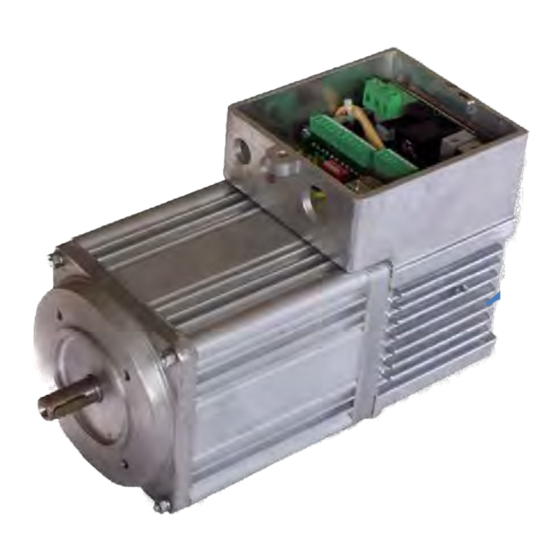
- Page 1 Asynchronous Positioning Motor with integrated frequency inverter and optional keypad Software V 42.xx KFM05a ..Instruction Manual SIEI-AREG GmbH Technical subjects to change without notice Art.-Nr.: 918 111e Rev: 09 / 14...
- Page 2 CERTIFICATE The Certification Body of TÜV SÜD Management Service GmbH certifies that SIEI-AREG GmbH Gottlieb-Daimler-Str. 17/3 74385 Pleidelsheim Germany has established and applies a Quality Management System for Development, Production and Marketing of Electronically Controlled Drive Systems. An audit was performed, Report No. 70013772 Proof has been furnished that the requirements according to ISO 9001:2008...
-
Page 3: Gottlieb-Daimler-Straße
The information provided herein is only provided for product description and cannot be taken as an insured property in the legal sense. Thank you for purchasing this GEFRAN-product. We are always pleased to receive your suggestions to improve the KFM05a and this manual at info@sieiareg.de. More information can be found at www.sieiareg.de. - Page 4 SIEI-AREG GmbH Gottlieb-Daimler-Straße 17/3 74385 Pleidelsheim Germany Fon: +49 7144 89736 0 Page without content Art.-No.: 918 111e Page 4 von 60 Rev. 09/14...
-
Page 5: Table Of Contents
About this Manual ........................... 3 General Safety notes ........................8 1. General ............................. 10 1.1 Applications ......................... 10 1.2 Technics of the KFM05a ...................... 10 2. Technical Data .......................... 11 2.1 Datasheet ..........................11 2.2 Speed- / Torque Characteristics ..................12 2.3 Mechanical Load of the Motor Shaft .................. - Page 6 SIEI-AREG GmbH Gottlieb-Daimler-Straße 17/3 74385 Pleidelsheim Germany Fon: +49 7144 89736 0 3. Connections Display- an Controller-Elements ................22 3.1 Overview of the Terminals (controller version 3) ..............22 3.1.1 Mains Connection X12 ....................23 3.1.2 Fuse F1 ......................... 23 3.1.3 Terminal X7 ........................
- Page 7 SIEI-AREG GmbH Gottlieb-Daimler-Straße 17/3 74385 Pleidelsheim Germany Fon: +49 7144 89736 0 4. Description of functions ......................36 5. Working with E@syDrive ......................37 5.1 Software and installation...................... 37 5.2 Connection and interface ..................... 37 5.3 How to start E@syDrives ..................... 38 5.4 Configurator E@syDrives ....................
-
Page 8: General Safety Notes
SIEI-AREG GmbH Gottlieb-Daimler-Straße 17/3 74385 Pleidelsheim Germany Fon: +49 7144 89736 0 General Safety notes Read and observe this technical description before commencing assembly and commissioning work. General Depending on their type of protection power drive-converters can have live, bare, possibly moving or rotating parts and a hot surface during operation. - Page 9 SIEI-AREG GmbH Gottlieb-Daimler-Straße 17/3 74385 Pleidelsheim Germany Fon: +49 7144 89736 0 General Safety notes Electrical Connection When working on a live drive-converter observe the valid national accident prevention regulations (e.g. BGV A2). Electrical installation is to be made according to the relevant regulations (e.g. line cross sections, fuses, PE-connection).
-
Page 10: General
The program is stored in the FLASH-ROM, so standard software resp. customer specific software can be loaded resp. changed in a simple way without handling the KFM05a, also by the customer (it is possible to save the program), because a basic software (boot sector) remains in the KFM05a. -
Page 11: Technical Data
74385 Pleidelsheim Germany Fon: +49 7144 89736 0 2. Technical Data 2.1 Datasheet Type KFM05a / 180 KFM05a / 310 KFM05a / 510 KFM05a / 500L Power supply 230 Vac ±10 % / 50 Hz ±10 % Netz Nominal current... -
Page 12: Speed- / Torque Characteristics
FA = 140 N These forces should not to be exceeded! Warning! If the KFM05A is coupled via belts (flat-, V- or tooth-belt), the belt-tension must be adjusted in that way, that the radial forces are not exceeded. Art.-No.: 918 111e Page 12 von 60 Rev. -
Page 13: Motor Dimension
SIEI-AREG GmbH Gottlieb-Daimler-Straße 17/3 74385 Pleidelsheim Germany Fon: +49 7144 89736 0 2.4 Motor Dimension Art.-No.: 918 111e Page 13 von 60 Rev. 09/14... -
Page 14: Order Number For Kfm05A
SIEI-AREG GmbH Gottlieb-Daimler-Straße 17/3 74385 Pleidelsheim Germany Fon: +49 7144 89736 0 2.5 Order number for KFM05a 2.5.1 Code definition KFM05a Power special design 180 W asynchronous motor 310 W asynchronous motor 500 W asynchronous motor (with fan) 510 W asynchronous motor... -
Page 15: Additional Ordering Information
2.5.2 Additional ordering information: Gear detailed description Varnishing - Standard not varnished (aluminum cast) - Standard varnishing KFM05A L 500 black - Special varnishing on request Software - Standard software on CD-ROM (manual as PDf-file) - Customer specific software (detailed description) on request... -
Page 16: Housing
To facilitate rapid connection of the KFM05a, all ports are provided with plastic bushing in this version. Light version 2.6.2 IP65 metric screwing without shaft sealing This version of the KFM05a is additionally sealed to IP65. Since no shaft seal is provided, IP65 protection can only be achieved with built-on gear box. Art.-No.: 918 111e Page 16 von 60 Rev. -
Page 17: Housing With Ip54 Heavy Metal Bushing Connectors
Fon: +49 7144 89736 0 2.6.3 Housing with IP54 heavy metal bushing connectors To facilitate rapid connection of the KFM05a, all ports are provided with metal bushing in this version. Heavy Version 2.6.4 Housing with D-Sub 9 connector on the right side IP20 In this version, there is a D-Sub 9 connector on the right side of the housing for communication via a fieldbus or RS232. -
Page 18: Ip54 Metric Screwing With Fieldbus Via M12
Fon: +49 7144 89736 0 2.6.6 IP54 metric screwing with fieldbus via M12 This housing of the KFM05a has four metric holes for cable inlet respectively connectors: 1 x M20, 1 x M16 and 2x M12 for fieldbus connection. 2.6.7 Housing closed, connection made by client This option, gives the client the possibility to make his own connection layout. -
Page 19: Mounting Hints
Fon: +49 7144 89736 0 2.7 Mounting Hints There must be a minimum distance to neighboring units, motors, walls, etc. to ensure a sufficient cooling of the KFM05a. KFM05a /180 / 310 / 510 KFM05a /500L Art.-No.: 918 111e Page 19 von 60... -
Page 20: Options
2.8.2 Option Safety relay As an option, a safety relay can be installed at the factory. This is necessary if the KFM05a should be used in applications in which security features are required. The safety relay can be activated with the enable input X7:7 and then turns on the IGBT output. -
Page 21: Option Additional 24V Power Supply
“KFM05a / xxx! External 24V supply” is set. 2.8.5 Option analog output In some applications it is required to pass the information about the status of the KFM05a to other devices. For this, the KFM05a can optionally provide two 0-5V analog outputs. The source if the signal can be chosen in the menu. -
Page 22: Connections Display- An Controller-Elements
Steckern / Buchsen zum schnellen und einfachen wechseln am Gehäuse. The KFM05a is available in different versions, either with screwing / inlets / without openings for direct connection to the terminals in the interior (Section 2.6) or male / female connectors for quick and easy change on the housing. -
Page 23: Mains Connection X12
SIEI-AREG GmbH Gottlieb-Daimler-Straße 17/3 74385 Pleidelsheim Germany Fon: +49 7144 89736 0 3.1.1 Mains Connection X12 Mains connection (230 VAC ± 10 %) at terminal X12 with standard-cable A > 0, 75 mm 2 , e.g.: H05VV-F 0, 75. The connection of the cable must be protected external. Mains filter 3.1.2 Fuse F1 The drive is protected with 5 A medium (fuse 5 x 20). -
Page 24: Terminal X7
Input 5 (X7:7) acts directly on the power amplifier, therefore it has always to be active, if the KFM05a gets active. The reference potential is set via jumper ST3. State of delivery ST3 in the back, reference X7:2, 0 V. No reference to GND or PE. The function of the inputs 1 – 4 are defined by software. -
Page 25: Terminal X6
SIEI-AREG GmbH Gottlieb-Daimler-Straße 17/3 74385 Pleidelsheim Germany Fon: +49 7144 89736 0 3.1.4 Terminal X6 21. Output 1 potential free 25. NC Relay Ready 22. Output 2 potential free 26. NO Relay Ready 23. Output 3 potential free 27. Option safety relay 24. -
Page 26: Jumper St3
SIEI-AREG GmbH Gottlieb-Daimler-Straße 17/3 74385 Pleidelsheim Germany Fon: +49 7144 89736 0 3.1.5 Jumper ST3 With this jumper, the logic of the inputs is defined. FRONT = 24V reference X7:1 BACK = GND reference X7:2, standard Therewith, the inputs can be adjusted to any controller as described below. The default configuration (BACK) corresponds to the connection examples. -
Page 27: D-Sub 9 Connector X18 (St3)
GND is connected internally with PE = ground. ATTENTION ! Put the D-Sub socket into the KFM05A in a way that the plug will not be damaged (bending, breaking off) and no parts can fall into the electronics. Art.-No.: 918 111e Page 27 von 60 Rev. -
Page 28: Option Holding Brake Terminal X4
X5 If the brake is controlled via the KFM05a, the brake is directly connected to the connector X3 on the board. To open the brake, it is supplied with 0.5 A via the terminal X7:1 +24 Vdc and X7:2 GND. -
Page 29: Option Fieldbus Terminal X
SIEI-AREG GmbH Gottlieb-Daimler-Straße 17/3 74385 Pleidelsheim Germany Fon: +49 7144 89736 0 3.1.12 Option fieldbus terminal X Currently under development 3.1.13 Recommended connection terminal For simple applications +15 V not stabilized of X7:13 and X7:14 can be used. Do not forget the connection of X7:14 and X7:2, the maximum current may not more than 100 mA. -
Page 30: Overview Of The Plugs (Light Version)
Pin PE earth conductor Choose a fuse according to the used cable, e.g. 16A for 1,5 mm² cable. Additionally the KFM05a has to be grounded at the earth bolt with minimum 10 mm² cable. 3.2.2 Control connection ST2 digital signals Control connection via ST 2 type P X0412 Bulgin. -
Page 31: Rs 232 Connection St 3
The RS 232-interface is led to plug ST 3 (type M8 bushing 4 pins), the assignment is described below. ATTENTION Before connecting PC and KFM05A ensure that there are no potential differences by ground loops or electrostatics. Use a commercial RS 232 data isolator for more safety for PC and KFM05A. -
Page 32: Status Led
(PE) or earth potential. 3.2.8 Cable Clance M12 The cable clance is used to connect the power supply of the fan for the KFM05a/500L. 3.2.9 Connection advice light version Art.-No.: 918 111e Page 32 von 60 Rev. -
Page 33: General Overview On The Connectors In The Heavy Version
Mains connection at ST 1 with plug type SC 6-pole (5 + PE) CONINVERS and standard-cable with A > 1,5 mm², e.g. H05VV-F1,5. Choose a fuse according to the used cable. Additionally the KFM05A has to be grounded at the earth bolt. A coupling can be ordered with SIEI-AREG-order-No. 166194. -
Page 34: Rs 232 Connection St 3
(PE) or earth potential. Cable minimal 10 mm² 3.3.7 Cable Clance M12 The cable clance is used to connect the power supply of the fan for the KFM05a/500L. 3.3.8 Option fieldbus connector ST 4 The fieldbus (for example CANopen) is led to this connector (type Sub-D 9). -
Page 35: Connection Advice Heavy Version
SIEI-AREG GmbH Gottlieb-Daimler-Straße 17/3 74385 Pleidelsheim Germany Fon: +49 7144 89736 0 3.3.9 Connection advice heavy version Art.-No.: 918 111e Page 35 von 60 Rev. 09/14... -
Page 36: Description Of Functions
So in many applications a PLC is not necessary on account of the extensive possibilities for parameterizing the drive. The input enabling always has to be active, if the KFM05a is in operation, because this input enables directly the power amplifier. If this input is inactive the power amplifier is blocked and the drive becomes torque less (resp. -
Page 37: Working With E@Sydrive
/service“. Under “www.sieiareg.de” there is the actual information about the KFM05A and other products of SIEI-AREG. 5.2 Connection and interface For the connection between KFM05A and PC a cable with at least 3 lines (RxD, TxD and GND) must be used (see chapter 3.1.8). ATTENTION ! Before connecting PC - KFM05A switch off both devices to avoid damaging the interface by potential differences, ground loops or electrostatics. -
Page 38: How To Start E@Sydrives
After the start following menu appears: By clicking the picture of the KFM05a you will reach a page, where the desired KFM05a-versions for loading the appropriate parameter-file KFM05a.PAR can be clicked. Art.-No.: 918 111e Page 38 von 60 Rev. - Page 39 A set of parameters can have any name, but it must have the extension .PAR. Self-created parameter-files must be saved in the same directory (e.g.: C:\Programme\SIEI PC Tools\KFM05a\ KFM42#03\E@syDrives) as the delivered basic-parameter-file KFM05a.PAR. Please be careful about the correct version-affiliation (e.g. KFM42#03) and the language-version ( (E@sy Drive_German = German, E@sy Drive = English) ! Art.-No.: 918 111e...
-
Page 40: Configurator E@Sydrives
Fon: +49 7144 89736 0 5.4 Configurator E@syDrives To load a parameter file, 2 to enable or disable connection to KFM05A, 3 e.g. to set and control the interface, 4 e.g. to activate the program „KFM LOAD“ (it is used to load another software-version (firmware) into the KFM05a, see chapter 8.), 5 to save a changed parameter into... -
Page 41: Help-Text
SIEI-AREG GmbH Gottlieb-Daimler-Straße 17/3 74385 Pleidelsheim Germany Fon: +49 7144 89736 0 5.4.1 Help-Text To activate the help-text click a parameter and then press F1 or click the active text, if exist. Example: 2nd parameter page parameter f1 (max) Art.-No.: 918 111e Page 41 von 60 Rev. -
Page 42: Motor Test On The Diagnosis Page
Fon: +49 7144 89736 0 5.4.2 Motor test on the Diagnosis Page The window „Motor test“ can be used to start and test the KFM05A via PC without extensive wiring. A connection between X7:14 and X7:2 and between X7:13 X7:7 enables the power amplifier, jumper J has to be BEHIND. -
Page 43: Input Functions
SIEI-AREG GmbH Gottlieb-Daimler-Straße 17/3 74385 Pleidelsheim Germany Fon: +49 7144 89736 0 5.5 Input functions 01 : 8 positions per In1 / In2 / In4, if In3 If In3 = 1, In1, In2 and In4 select the positions Pos.1 to Pos.8. If In3 = 0, In1, In2 and In4 select the frequencies f1 to f3 (no positioning) 02 : 8 positions permanent via In1 / In2 / In4 In1 / In2 / In4 select the positions Pos.1 to Pos.8, In3 can be used e.g. - Page 44 The started door-actions are continuing, even if the input goes inactive, until the next input command appears. With DIP-switch DIP 4 of the KFM05a this door-function can be switched to the time-controlled closing-function (automatic operation as 17) without changing the input wiring. The door-width can be learned via special teach-in-function.
-
Page 45: Position Control
SIEI-AREG GmbH Gottlieb-Daimler-Straße 17/3 74385 Pleidelsheim Germany Fon: +49 7144 89736 0 5.6 Position control The following graphic illustrates how position control functions: Motor frequency f depends on sign and magnitude of the position deviation: f = position deviation × P-freq. VF-operation characteristic depends on the magnitude of position deviation: = magnitude of position deviation ×... -
Page 46: Fault Messages And Fault Treatment
SIEI-AREG GmbH Gottlieb-Daimler-Straße 17/3 74385 Pleidelsheim Germany Fon: +49 7144 89736 0 6. Fault Messages and Fault Treatment Open the alarm-menu with -button to display a possibly existing fault: Here it is possible to display the last 64 fault messages (button “History”). The function „Reset alarm”... -
Page 47: Program Kfm_Load
- With an icon in the same manner as program E@syDrive (see chapter 5.3 page 21) - Out of the program E@syDrive: - Interrupt the connection to the KFM05A 1 , the last row of E@syDrive will show „OFF LINE“ - Menu-command „Service“ 2 , function „Tools“, KFM_LOAD Art.-No.: 918 111e... -
Page 48: Option Keypad
Keypad as delivered Keypad in real size 8.2 Controls and display functions 8.2.1 Status LED of the Keypad The status of the KFM05a is displayed via LED on the Keypad. GEFRAN ILim Significance of the LED BRK:... -
Page 49: Display Of The Keypad
42.03.00 8.2.3 Keys of the keypad The navigation through the menus and parameters is done with the keys. The functions of the KFM05a are not yet triggered with it. Some keys have no function in this version. - Escape DISP... -
Page 50: Functions Of The Keys
SIEI-AREG GmbH Gottlieb-Daimler-Straße 17/3 74385 Pleidelsheim Germany Fon: +49 7144 89736 0 8.2.3.1 Functions of the keys On the menu level, the menu point can be chosen with the arrow keys ▲ and ▼. ▲ - On the parameter level and active input, increase value. ▼... -
Page 51: Operator Menu And Function
SIEI-AREG GmbH Gottlieb-Daimler-Straße 17/3 74385 Pleidelsheim Germany Fon: +49 7144 89736 0 8.3 Operator menu and function Monitor - menu Monitor The status row displays the current status Freq-Steuerung “0” means no error Positionierung Status: Status: Display of the parameter in the Monitor menu Monitor menu only displayed value Monitor Drehzahl... -
Page 52: Structure Of The Menu
SIEI-AREG GmbH Gottlieb-Daimler-Straße 17/3 74385 Pleidelsheim Germany Fon: +49 7144 89736 0 Error memory: In the menu item error memory, the last 10 errors can be displayed. To read the errors, they must be readout the EEPROM. When "neu auslesen" is changed from 0 to 1, the readout is activated and the last error will be displayed under “Feher 0”. -
Page 53: Freq-Steuerung (Setpoint)
SIEI-AREG GmbH Gottlieb-Daimler-Straße 17/3 74385 Pleidelsheim Germany Fon: +49 7144 89736 0 8.4.2 Freq-Steuerung (Setpoint) f1min (frequency setting f1min, Hz) f1(max) f2min f2(max) f3min f3(max) Beschlg. pos. (acceleration pos., Hz/s [accp]) Verzoeg. pos (delay pos., Hz/s [decp]) Beschg. neg. (acceleration neg., Hz/s [accn]) Verzoeg. -
Page 54: Positionierung (Positioning)
SIEI-AREG GmbH Gottlieb-Daimler-Straße 17/3 74385 Pleidelsheim Germany Fon: +49 7144 89736 0 8.4.4 Positionierung (positioning) Geschw. V1 (positioning speed 1, Hz) Geschw. V2 (positioning speed 2, Hz) Geschw. V3 (positioning speed 3, Hz) Geschw. V4 (positioning speed 4, Hz) Geschw. V_ref (speed homing, Hz) Wartezeit T1 (dead time T1, s) -
Page 56: Ec Declaration Of Conformity
Asynchrony -Positioning motor with Inverter Typbezeichnung / KFM05a /180 KFM05a /310 KFM05a /500L KFM05a /510 Type Die Übereinstimmung des bezeichneten Produkts mit den Vorschriften der Richtlinien EMV 2004/108/EG, NSR 2006/95/EG wird nachgewiesen durch die vollständige Einhaltung folgender Normen: Conformance of the product with the Directive EMC 2004/108/EC, LVD 2006/95/EC is given to the following standards: Harmonisierte, europäische Normen EMV-Richtlinien... -
Page 58: Ec Declaration Of Incorporation
Asynchrony -Positioning motor with Inverter Typbezeichnung / KFM05a /180 KFM05a /310 KFM05a /500L KFM05a /510 Type Die Übereinstimmung des bezeichneten Produkts mit den Vorschriften der Maschinenrichtlinie 2006/42/EG, wird nachgewiesen durch die vollständige Einhaltung folgender Normen: Conformance of the product with the Machinery Directive2006/42/EC is given to the following standards: Harmonisierte, europäische Normen EMV-Richtlinien... - Page 59 Note: ……………………………………………………………………………………………………………………………… …..……………………….………………………………………………………………………………………………… ……………………………………………………………………………………………………………………………… ……………………………………………………………………..…………………………………………….………… ……………………………………………………………………………………………………………………………… ……………………………………………………………………………………………………………………………… ……………………………………………………………………………………………………………………………… ……………………………………….………………………………………………………………………….………….. ……………………………………………………………………………………………………………………………… ……………………………………………………………………………………………………………………………… ……………………………………………………………………………………………………………………………… ……………………………………………………………………………………………………………………………… ……………………………………………………………………………………………………………………………… ……………………………………………………………………………………………………………………………… ……………………………………………………………………………………………………………………………… ……………………………………………………………………………………………………………………………… ……………………………………………………………………………………………………………………………… ……………………………………………………………………………………………………………………………… ……………………………………………………………………………………………………………………………… …………………………………………………………………………………………………………………………….. …………………………………………………………………………………………………………………………….. ……………………………………………………………………………………………………………………………… ……………………………………………………………………………………………………………………………… ……………………………………………………………………………………………………………………………… …………………………………………………………………………………..………………………………………….. ……………………………………………………………………………………………………………………………… ……………………………………………………………………………………………………………..………………. …………………………………………………………………………………………………………………..…….
Need help?
Do you have a question about the KFM05a and is the answer not in the manual?
Questions and answers