Table of Contents
Advertisement
Quick Links
Advertisement
Table of Contents

Related Manuals for Climax VCP-LTE


Summary of Contents for Climax VCP-LTE
- Page 1 VCP-LTE Voice Call Point Installation Guide Nov 19, 2021...
-
Page 2: Table Of Contents
3.4. PC P ) ________________________________ 8 OFTWARE NSTALLATION ROGRAMMING 3.4.1 Installing USB Driver ________________________________________________________________ 8 3.4.2 Installing PC Programming Tool _____________________________________________________ 8 PROGRAMMING VCP-LTE _______________________________________________________________ 9 PC P ) __________________________________________ 9 ROGRAMMING NSTALLERS 4.1.1 Profile __________________________________________________________________________ 11 4.1.2 SMS Program ___________________________________________________________________ 12 4.1.3... -
Page 3: Introduction
1. Introduction VCP-LTE is an AC-powered Emergency Voice Call Point, having one button that can be used to activate alarm and report events via Speech, SMS and IP (Mobile Network) protocols to directly communicate with the monitoring center. The medical alarm system can integrate with multiple devices/sensors: Wrist Transmitter, Emergency Pendant, Fall Sensor, PIR Motion Sensor, Panic Button, Smoke Detector, Water Leakage Sensor, and CO Sensors, etc. -
Page 4: Application Overview
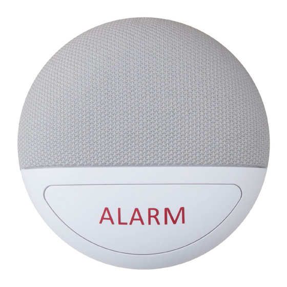
2. Application Overview 2.1. Parts Identification 1. ALARM Button 2. LED Indicator (Red) Flashes once every 2 seconds: Low Battery. Flashes once every 5 seconds: GSM fault. 3. LED Indicator (Green) Light on: AC Power on. Flashes once every 5 seconds: AC Fail. 4. -
Page 5: The Power Supply
AC failure, the Voice Call Point will make AC fail report. Backup Battery In addition to the AC power adapter, a rechargeable battery is installed inside VCP-LTE to serve as a backup in case of a power failure. -During normal operation, the AC power adapter is used to supply power to VCP-LTE and at the same time recharge the battery. -
Page 6: Getting Started
Do not insert a SIM card with a SIM card adapter or it will cause damage to the SIM card and its holder. 3.2. Mounting The VCP-LTE can be mounted on the wall or deployed on a flat surface. Wall Mounting Ensure VCP-LTE is fitted at approximately chest height where the button can be easily accessed and operated. - Page 7 3. Drill 2 holes and screw the bracket onto the wall. 4. Connect a DC 9V 1A SPS power adapter to DC jack of VCP-LTE and keep the cable well-placed. 5. Fit VCP-LTE onto the mounting bracket. Make sure the imprinted mark on VCP-LTE B is aligned with the upper mark on the bracket.
-
Page 8: Hardware Installation (For Pc Programming Tool)
3.3. Hardware Installation (For PC Programming Tool) To use PC Programming Tool for programming VCP-LTE, follow the hardware installation steps below: Step 1. Insert the device/cradle end of the Programming Micro-USB Cable into the Micro-USB jack as shown in the picture: Step 3. - Page 9 <WARNING> If programming cable is not provided, please contact your supplier. DO NOT attempt to connect VCP-LTE to computer with a regular Micro-USB cable. Programming Regular Micro-USB Micro-USB Cable Cable...
-
Page 10: Software Installation (For Pc Programming Tool)
3.4. Software Installation (For PC Programming Tool) 3.4.1 Installing USB Driver VCP-LTE can be programmed via USB port connection of a computer using the PC Programming Tool software (using the Programming Cable). If the computer cannot recognize the USB connection, please try installing the USB driver as instructed below. -
Page 11: Programming Vcp-Lte
The following configuration screen will be opened. Step 2. Select the following settings in the top section of the configuration screen and click “Open.” Port: Select the COM port generated for VCP-LTE after installing the USB Driver (the USB port connected to VCP-LTE). - Page 12 Step 3. Read Configuration To start configuring VCP-LTE settings, click on “Open”. A Read configuration success message will pop up, click “OK” to proceed: The current VCP-LTE setting will be displayed. Click on different tabs to see and edit VCP-LTE functions.
-
Page 13: Profile
VCP-LTE. Apply profile If you wish to apply all the configuration of a profile into VCP-LTE, go to each individual page and click on all the “Write” buttons to make sure all settings are programmed into... -
Page 14: Sms Program
VCP-LTE. Profile Manager Click on “Profile Manager” to manage the profiles: Delete Profile Select a profile and click on “Delete Profile”. A pop-up window will ask you to confirm the selection: Select “Yes” to delete the profile, or “No” to return to the previous page. -
Page 15: Apn
4.1.3 APN The APN setting must be completed for VCP-LTE to report events via cellular network. Click “APN” to set APN Name, APN User and APN Password and click “Write” to confirm. APN Name: The name of an access point for GPRS. Please ask your SIM card ... -
Page 16: Report
Enter a report destination. The format of the report destination will depend on the Reporting Format (Type). Please see Report Destinations below. If there are no report destinations programmed, VCP-LTE will not report after Guard Time expires. 2. Event Filter Select an event filter. - Page 17 For example: VCP-LTE being low on battery is a “status” event. If report index 3 and 5 are set as “status” and index 4 as “all” in event filters, this status event will be reported to destinations 3, 4, and 5.
- Page 18 Index 1 is successful. If reporting to Index 1 failed, VCP-LTE will carry on reporting to Index 4. VCP-LTE will try the report destinations within a group for up to 4 times in total. If all ...
- Page 19 4 tries), VCP-LTE will also terminate reporting. When reporting to the first group failed (going through all the Report Index within the group for 4 tries), VCP-LTE will start reporting to the next group. When reporting to the second group succeeds, reporting is regarded as successful.
- Page 20 SMS Report text format Below are the SMS Text messages sent to user according to the condition of the Base. SMS text table: VCP-LTE Condition SMS Text format Low battery status VCP Low Battery Battery voltage restored VCP Battery Restored...
-
Page 21: Setting
120: Panic Guard Time: The Guard Time will begin to count down when the Alarm Button of VCP-LTE is pressed. If a false alarm is triggered, it can be canceled during guard time by pressing and holding the Alarm Button for 5 seconds. - Page 22 After an alarm is reported to all the reporting destinations and at least one of them is successful, VCP-LTE` will start a waiting period (callback time) to auto answer any incoming calls. When VCP-LTE receives an incoming call within the callback timer, it will auto ...
- Page 23 After VCP-LTE is rebooted, reset or programmed, the system will start counting down the time for the first Auto check-in report. VCP-LTE will send the first check-in report according to the setting of Auto Check-In Offset time. Afterwards, VCP-LTE will send reports according to the...
- Page 24 a full-duplex Two-way communication. Incoming Call Check Access code: When set as “Disable”, VCP-LTE will auto answer an incoming call and open a full-duplex Two-way communication without checking the Access Code (default: 1111). When set as “Enable”, VCP-LTE auto answer an incoming call (after the first ...
-
Page 25: Device
Depends on the supplier, a Sensor ID of the device may be labeled (usually on the back of the device). Users can use the “Add Sensor” function to include sensors into the VCP-LTE. Click on the “Add Sensor” button: ... -
Page 26: Miscellaneous
number of GSM module will be displayed on the right side of GSM signal strength. Reboot Device Click “Reboot Device” to reboot VCP-LTE. This will not remove any programmed parameters on VCP-LTE. Reboot GSM Click “Reboot GSM” will reset the Cellular module. -
Page 27: Firmware
Total elapsed time will be displayed to show how long the updating process has elapsed. Step 3. When updating process is completed, a message “Firmware update success!” will be displayed in a pop-up window. Step 4. Click on “OK” and the programming tool will read the settings of VCP-LTE again. <WARNING> ... -
Page 28: Sms Remote Programming
Step 7. Enter a comma (,). Step 8. Enter the parameter(s). Step 9. The composition of the command is completed. You can send the command to VCP-LTE now. <NOTE> If the SMS message text format of your mobile phone is not English, please change it to English for SMS remote programming. -
Page 29: Local Rf Device Management
5. Local RF Device Management VCP-LTE can learn up to 20 RF devices which can be used to activate VCP-LTE to make emergency report. Entering Learning Mode Press the Alarm Button of VCP-LTE for 8 seconds. VCP-LTE will emit one beep at the second. -
Page 30: Operation
Programming Tool or SMS command. Default is disabled. Alarm Activation Press the Alarm Button of VCP-LTE to or press the Active Button of the learnt-in RF device (WTR, Fall Sensor or PB), or pull the cord of PCU to activate alarm. -
Page 31: Callback Mode
event cannot be cancelled after Guard Time Fall Sensor has expired. This function is only used when a fall is detected, if the Alarm Button on VCP-LTE or the Active Button of the learnt-in Fall Sensor is pressed to activate alarm, normal guard time is used instead. -
Page 32: Speech Reporting Method
Access Code or not before it opens a full-duplex Two-way communication. If the number of the incoming call matches any of the Caller ID, VCP-LTE will instantly pick up the call, emit one beep (at the caller handset) and open a two-way communication (without checking Access Code). - Page 33 The function of pressing sensor button to end call is now programmable via PC Programming Tool or SMS command. Default is disabled. At 20 and 10 seconds before the communication time expires, VCP-LTE will emit 1 beep via the telephone handset to alert the user.
-
Page 34: Appendix
To restart VCP-LTE. Remote Firmware FWUG FWUG:PROG,1111,59.124.230.221,53033,/img/123.bin,042d Upgrade Upgrade VCP-LTE firmware by downloading firmware file from server remotely. Parameter 1: Server IP Address (Max 44 characters) Parameter 2: Server Port Number Parameter 3: File path(max 31 characters) Parameter 4: crc16 check sum... -
Page 35: Contact Id Communications Protocol And Format
Contact ID Communications Protocol and Format VCP-LTE can communicate with the CMS receiver using the Contact ID protocol. The CMS can receive the event codes using SMS or IP reporting methods. The form of the CID message is: IP Reporting Data Format [ACCT <space>MT QXYZ GG CCC S... - Page 36 When Heat Detector (HD) is triggered. When Heat alarm is restored. 120 - Panic When the Alarm Button of the VCP-LTE is pressed (“Help Event” set as 120). 151 - Gas Emergency When gas alarm is triggered.
- Page 37 162 - Carbon Monoxide emergency When Carbon Monoxide Detector (CO) is triggered. When Carbon Monoxide alarm is restored. 301 - Panel AC Failure When AC power is disconnected, the Green LED will flash. When AC power is restored to the Control Panel. 302 - Panel Low battery ...
Need help?
Do you have a question about the VCP-LTE and is the answer not in the manual?
Questions and answers