
Subscribe to Our Youtube Channel
Related Manuals for Climax Mobile Lite-R8 Slim


Summary of Contents for Climax Mobile Lite-R8 Slim
- Page 1 Mobile Mates Smart Care System & 4G/LTE PERS Locator Installer’s Guide Sep 21, 2020...
-
Page 2: Table Of Contents
Table of Contents INTRODUCTION ........................1 1.1........................1 OBILE ATES ’ ......................2 1.2. S IN THE SYSTEM OVERVIEW ......................3 ....................... 3 2.1. DENTIFYING THE ARTS ........................5 2.2. OWER UPPLY GETTING STARTED ......................7 3.1. SIM C .................. - Page 3 4.3.1.4 Walk Test ..........................44 4.3.1.5 Webpage Walk Test........................ 45 4.3.1.6 Edit / Delete Device ........................ 46 4.3.1.9 PSS Control ..........................47 4.3.1.11 Surveillance ........................... 48 4.3.1.12 Blue Tooth ..........................49 Panel Status / Setting ....................50 4.3.2. 4.3.2.1 Panel Status ..........................50 4.3.2.2 Panel Setting ...........................
- Page 4 OPERATION ......................... 86 6.1......................... 86 OBILE Answering Incoming Calls ..................86 6.1.1. Current Operation Condition .................. 86 6.1.2................... 87 6.2. GPS/W OCATE UNCTION 6.2.1. GeoFencing ......................... 88 Alarm Activation ......................89 6.2.2. 6.1.5.1 Alarm Report Procedure ....................91 Callback Mode .........................
-
Page 5: Introduction
The Mobile Lite Medical Alarm covers the following models: Name Cellular Feature RF, Voice Prompt, GPS positioning, Mobile Lite-R8 Slim LTE/GPRS Wi-Fi positioning Built-in Fall Sensor, Voice Prompt, GPS Mobile Lite-R15 Slim LTE/GPRS positioning, Wi-Fi positioning... -
Page 6: What's In The Box
Base 18-LTE: The Base 18-LTE provides charging for Mobile Lite R8/R15/R18 Slim. It also acts as an independent LTE, Wi-Fi, and IP medical alarm system with RF and Bluetooth capability for indoor operation. 1.2. What’s in the Box Your Mobile Mates package includes the following items: Items ... -
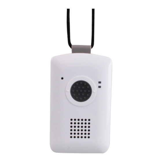
Page 7: System Overview
2. System Overview 2.1. Identifying the Parts Mobile Lite R8/R15/R18 Slim Button/LED/Compon Behavior Function/Indication 1. Microphone 2. Top LED (Green) Charging 1 flash every 5 seconds Normal Operation Top LED (Red) 1 Flash every 3 seconds Low Battery When Mobile Lite is charging, the Red LED will not indicate the battery status. - Page 8 Press and hold for 5 seconds during Terminate the call a call Press and hold for 8 seconds in Enter RF device learning mode normal mode Press twice in learning mode Remove all learnt device Press once in learning mode Exit learning mode 5.
-
Page 9: Power Supply
during a call Press and hold for 8 seconds Enter RF device learning mode in normal mode Press once in learning mode Exit learning mode Press twice in learning mode Remove all learnt device 3. Microphone 4. LED (Amber) All LEDs On During Remote Update 1 Flash every 3 seconds Low Battery... - Page 10 To Charge Mobile Lite, please refer to 3.5. Charging Mobile Lite. When Mobile Lite is low on battery, the Top LED will flash Red every 3 seconds and Mobile Lite will make Low Battery report. If battery is not changed after making Low Battery report, Mobile Lite will ...
-
Page 11: Getting Started
3. Getting Started 3.1. Mobile Lite SIM Card Insertion Step 1. Loosen the Cover Fixing Screws using a Philips screwdriver and remove the SIM Card Protective Cover. Step 2. Insert SIM Card into Mobile Lite, the chip side of the SIM card should face the back side of Mobile Lite as you insert the card. -
Page 12: Mobile Lite Belt Clip And Attachment
Put the lanyard around the neck of the user. Removal Press the button to release the hook and remove the lanyard. 3.3. Mobile Lite Belt Clip and Attachment Attachment Hook the the belt clip onto the Mobile Lite unit. ... -
Page 13: Base 18-Lte Installation
Use the clip to attach the Mobile Lite to the user’s waistband or belt. Removal Press the button to release the hook and remove the belt clip. < > < > When the fall detection function is enabled for Mobile Lite (R15, 18), please use the lanyard to wear Mobile Lite unit on the neck and let it hang in front of the chest, so that Fall Sensor can be effectively triggered. -
Page 14: Charging Mobile Lite
back of the Base. Step 7. Place the Base at the desired locaiton, and press firmly for 30 seconds to ensure good contact. 3.5. Charging Mobile Lite Step 1. Connect the Base 18-LTE to AC power to power up the base. Step 2 Press the lock release button to open the Mobile Lite slot cover. - Page 15 Never use a regular micro USB cable for computer connection. Programming Regular Micro-USB Micro-USB Cable Cable To use PC Programming Tool for programming Mobile Lite, follow the hardware installation steps below: Step 1. Place Mobile Lite into the CT-6 Cradle. Please make sure that the programming Contact Plates (of both Mobile Lite and the cradle) are in contact with each other.
-
Page 16: Hardware Installation For Lan Programming (Base 18-Lte)
Step 3. Insert the programming end of the Programming Micro-USB Cable into a computer USB port as shown in the picture below: 3.7. Hardware Installation for LAN programming (Base 18-LTE) The base 18-LTE can be programmed by accessing the built-in webpages via Local Area Network. -
Page 17: Software Installation
3.8. Software Installation 3.8.1. Installing USB Driver Mobile Lite Slim can be programmed via USB port connection of a computer using the PC Programming Tool software (using the Programming Cable). If the computer cannot recognize the USB connection, please try installing the USB driver as instructed below. - Page 18 IP cable into the Base 18-LTE’s Ethernet port and connected the cable to an Ethernet network for the Base to operate via Ethernet. Step 1. Download the Finder software from Climax’s website. Step 2. Click on “Finder” to initiate the installation.
- Page 19 Step 7. The Finder software will search for your Base on the LAN and display its information including IP Address, Firmware Version and MAC Address. Step 8. If the Base’s information is not displayed, click on “Search” for the software to start searching for a recognized IP address within the local network service.
-
Page 20: Programming
4. Programming Mobile Lite can be programmed by sending SMS commands to the device or using a PC Programming Tool. 4.1. PC Programming Tool (Programming Mobile Lite) For system setting programming with PC Programming Tool software via USB port, follow instruction below. Step 1. - Page 21 Step 2. Select the following settings in the top section of the configuration screen and click “Open.” Port: Select the COM port generated for Mobile Lite after installing the USB Driver (the USB port connected to Mobile Lite). Baud rate: 115200 ...
-
Page 22: Profile
4.1.1. Profile The Profile function allows you to create and edit different setting profiles which can be easily accessed in the future for quick programming. Current Setting After reading the configuration of Mobile Lite, the Profile scroll down bar will now display “Current Setting”... - Page 23 Apply profile If you wish to apply all the configuration of a profile into Mobile Lite, go to each individual page and click on all the “Write” buttons to make sure all settings are programmed into Mobile Lite. Profile Manager Click on “Profile Manager”...
-
Page 24: Sms Program
4.1.2. SMS Program This tab allows the user to program SMS Keyword (15 characters max.) and Access Code 1 (4-8 digits) which are used for SMS Programming feature. Enter the information and click “Write” to complete programming. Please note that SMS Keyword is case-sensitive. For detail information, please refer to 4.2. SMS Programming. -
Page 25: Report Setting
4.1.4. Report Setting The “Report” tab allows the user to configure report settings. Mobile Lite reports over 3 media: IP (Mobile Network), Speech channel, and SMS message. 5 Report Indexes are available for setting: 4 programmable settings are available per Report Index: 1. - Page 26 AccountNumber: Enter 4 to 23 alphanumeric account number assigned by CMS. Server: Enter either the IP address or the domain name of receiver. Port: Separate from Server with a colon “:”, then enter the port number Example : 0001@59.124.123.66:50123 For XML Report Format, you can also enter http://AccountNumber@server url or https://AccountNumber@server url AccountNumber: Enter 4 to 23 alphanumeric account number assigned by...
- Page 27 3 options: “All”, “Emergency” and “Status”. When an event is triggered, it will be reported to the reporting destination according to the setting. If set to All, the Mobile Lite will report all events regardless of event type. For example: Mobile Lite being low on battery is a “status”...
- Page 28 Group The Reporting Group determines the sequence of reporting. One Report Index can only be assigned to one Group. Reporting within a Group: If there are multiple Report Indexes programmed within a Group: Mobile Lite will report according to the numeric order (e.g. 1 > 2 > 3, etc.) ...
- Page 29 If reporting to Group 3 is successful, Mobile Lite will terminate reporting. If reporting to Group 3 is unsuccessful (going through all the Report Indexes within the group for 3 times), Mobile Lite will also terminate reporting. When reporting to the first group failed (going through all the Report Indexes within the group for 3 times), Mobile Lite will start reporting to the next group.
- Page 30 SMS text table: Mobile Lite Condition SMS Text format Low battery status Mobile Lite Low Battery Battery voltage restored Mobile Lite Battery Restored Wakes up time Mobile Lite Periodic Test GPS signal lost Mobile Lite GPS Signal Failure Carrier leaves GeoFence area Mobile Lite has exit GeoFence Area Carrier enters GeoFence area Mobile Lite has entered GeoFence...
-
Page 31: Geo-Fence
4.1.5. Geo-fence The “Geo-fence” tab allows the user to setup a GeoFence area. When GeoFencing is enabled, Mobile Lite will check its location every 2 minutes. If the user leaves the GeoFence area and is detected while Mobile Lite is ... - Page 32 to the mechanics of GPS positioning, the 6 decimal point may deviate slightly from the entered value. However, the actual position is affected very slightly. Radius: Enter the radius of the operational area with respect to the center of the operational area (200 to 10,000 meters). Click on “Write”...
- Page 33 polygon operational areas can be set up. Polygon Vertex Number: Select the number of vertices the polygon will have (3 or 4). If 3 is selected, Latitude4 and Longitude4 will dim to prevent selection. Latitude 1-4: Enter the location latitude of 1-4 vertices of the operational area (-90 to 90).
-
Page 35: Setting
4.1.6. Setting The Setting tab allows you to program general configuration for Mobile Lite. Click “Write” when you have completed all settings to confirm. Help Event (Selecting an event code): You can select the event code to be sent to the CMS when the Active ... - Page 36 Sensor has expired. This function is only used when a fall is detected, if the Active Button on Mobile Lite or the Active Button of the learnt-in Fall Sensor is pressed to activate alarm, normal guard time is used instead. Speech Report Ack: ...
- Page 37 When set as “Enable”, Mobile Lite auto answer an incoming call (after the first ring) within the callback timer, and wait for the correct Access Code (default: 1111) and # key entry within 15 seconds before it opens a full-duplex Two-way communication. If the correct Access Code (and the # key) are not entered within 15 seconds, the system will disconnect the call automatically.
- Page 38 When this function is set to “Off”, silent mode is turned off. When Mobile Silent is enabled, a Listen-in only communication will be established initially for Speech Reporting. The call recipient can enter DTMF keys to change communication types (please refer to 6.5.
- Page 39 Select to enable or disable the fall detection function of Mobile Lite. AGPS Select to enable or disable APGS (Assisted GPS) for Mobile Lite. When APGS is enabled (Factory Default), data connection will be used to contact the assistance server for AGPS information to improve the performance of GPS.
- Page 40 from 0-60 minutes. When set as 0, Mobile Lite will not update or report GPS location, continuous GPS Report function is disabled For example, if Report Period is selected as “1 hour” and Report Interval set as “3 minutes”, Mobile Lite will keep checking and reporting GPS location every 3 minutes during the 1 hour-period after Geofence Alarm.
-
Page 41: Device (R8, R18 Only)
4.1.7. Device (R8, R18 Only) Click on the “Device” tab for Device settings where you can view device zone, type, add or remove devices. For learning new device(s), please use local learning mode or use the PC Programming Tool. Add Sensor: Depends on the supplier, a Sensor ID of the device may be labeled (usually on the back of the device). -
Page 42: Miscellaneous
4.1.8. Miscellaneous Click on the “Misc.” tab to program miscellaneous options: Signal Strength Click on the Signal Strength button to obtain GSM signal strength. The IMEI number of GSM module will be displayed on the right side of GSM signal strength. -
Page 43: Firmware
4.1.9. Firmware To update the firmware of Mobile Lite: Step 1. Click “Firmware”. Step 2. Select the firmware update speed from the drop down menu. The shorter the time, the faster the update speed; however some computer may not be able to support high update speed and doing so may crash the computer. -
Page 44: Sms Remote Programming For Mobile Lite Slim & Base 18-Lte
4.2. SMS Remote Programming for Mobile Lite Slim & Base 18-LTE Please change the language setting of your mobile phone to English before you proceed with SMS remote programming. Step 1. Enter the SMS screen on your mobile phone or smartphone. Step 2. -
Page 45: Lan Programming For Base 18-Lte
4.3. LAN Programming for Base 18-LTE Base 18-LTE can be programmed by accessing the built-in webpages via Local Area Network. Step 1. From the Finder software, select the Base and click “Open Webpage”, or simply double click on the Base. Step 2. -
Page 46: Device Management
RF device: All Climax RF devices are supported. IP Cameras: The Base 18-LTE is compatible with Climax VST-1818 Series IP Camera. Up to 6 IP Cameras are supported. Bluetooth Device: Available for models with built-in Bluetooth module only. -
Page 47: Webpage Learning
4.3.1.2 Webpage Learning Select Device Management – Learning/Inclusion from base webpage. Step 1. Click “Start” to enter learning mode. Step 2. Press the learn button on each device to transmit learn code. < > < > For IP Camera VST-1818 Series, press and hold the Privacy button for 10 seconds. -
Page 48: Add Rf Devices
Step 5. If the device is successfully learnt into the system, the added device will be displayed in the “Learned Device” section. After learning in all devices, click Stop to exit learn mode. The system will automatically exit Learn mode if left idle for 5 minutes. 4.3.1.3 Add RF Devices RF device may be added into base without transmitting learn signal by entering the device’s RF code via base webpage. -
Page 49: Webpage Walk Test
operational range. Step 4. Press and hold the help button for 8 seconds again to exit learning mode. Alternatively, the base will exit learning mode automatically after 5 minutes of inactivity. 4.3.1.5 Webpage Walk Test Select Device Management – Walk Test from base webpage. Step 1. -
Page 50: Edit / Delete Device
4.3.1.6 Edit / Delete Device Select Panel from base webpage to access base device list. Edit Device Click “Edit” from the device entry under Device List to edit device info. Enter or select the device information and click OK to confirm. Name: ... -
Page 51: Pss Control
Tag List” under PSS Control. See 4.3.1.9 PSS Control for details. Zone: Select the Device zone number. Trigger Response When the device is triggered, the Base will activate selected Home Automation Scene number. Please refer to 4.3.5.3 Scene webpage for detail. -
Page 52: Surveillance
Click Delete to remove power switch from base. Click Switch On/Switch Off to turn on/off power switches. Or click Switch Toggle to toggle between on/off status. For Power Switch Dimmer, you can also set its power output level with the slide down menu. ... -
Page 53: Blue Tooth
For IP Camera, click “View” or “Setting” to access IP Camera webpage for video streaming or setting configuration. A new webpage will open and you will be required to enter the username and password for the IP Camera to access streaming or setting. -
Page 54: Panel Status / Setting
4.3.2. Panel Status / Setting 4.3.2.1 Panel Status Click “Panel” to enter panel status page. Panel Status: The panel operation status is displayed. If any faulty condition is detected, the corresponding status will turn red to indicate an error. Device List: ... -
Page 55: Panel Setting
4.3.2.2 Panel Setting Click “Panel Setting” to enter setting page. AC Fail Report: Set the waiting time before the Base reports to Central Monitoring Station when AC failure is detected. AC Fail Suspend: After AC failure is detected, the Base will enter sleeping mode and wake up ... - Page 56 report will be made according to Offset Period setting. This is used to test whether the CMS is able to receive the report from the base accurately. After this test report is sent, the Base will then send reports at regular ...
- Page 57 Speaker Volume: Select a preferred speaker volume level for the base. (There are 6 levels for selection. The higher the value is, the higher the volume level.) Silent Panel & Device Off: The base will sound beep and flash LED normally when it is activated ...
-
Page 58: General Setting
When disabled, the base will not check Access Code and will enter two-way communication straight away. Report Retry: On: When selected, the base will keep trying reporting until one reporting is successful. If reporting fails for three times in a row, the base will pause for 5 minutes before it starts reporting again. - Page 59 Guard Time: Non-Fall Sensor: Guard time normal is designed for any compatible sensor except for Fall Sensor (fall detection). The base will emit quick beeps during guard time. Alarm can be canceled during guard time by pressing and holding the Base Help Button for 5 seconds.
-
Page 60: Callback Access Code
4.3.3. Callback Access Code The Callback Access Code is used for incoming caller to establish two-way voice communication with the base during Call-back. When dialing to the base during call-back, the dialer should enter correct Callback Access Code for the base to pick up the call. -
Page 61: Network Setting
4.3.4. Network Setting 4.3.4.1 GSM Select Network Setting - GSM from base webpage Telephone Enter the Telephone number of the SIM card, then press OK. (Please refer to 7.6. Alarm session and Call Setup Methods for SCAIP Report. - Page 62 <crd>gsm:telephone number<crd> needs to be defined in this filed.) Check SIM This is designed for the system to check the SIM card or not. (If users do not intend to use the GSM funciton, please select “NO” to ensure the system will not check if the SIM card is inserted or not and it will not display the GSM fault by LED flashing.) GPRS...
- Page 63 For sending remote commands to system via SMS message, a personalized password is required for the baseto recognize your authority. SMS Access Code Program Access Code is used to recognize the identity of a valid user; and to give authority for Remote Installing (through SMS Text) or Remote Upgrading purposes (through GPRS).
-
Page 64: Network
4.3.4.2 Network Select Network Setting – Network from base webpage. This webpage is for you to program the Network for IP connection. Obtain an IP address automatically (DHCP) If DHCP is selected, the Network will obtain an IP address automatically with a valid Network DHCP Server. -
Page 65: Upnp
4.3.4.3 UPnP Select Network Setting – UPnP from base webpage. UPnP is Universal Plug and Play, which opens networking architecture that leverages TCP/IP and the Web technologies to enable seamless proximity networking in addition to control and data transfer among networked devices in the home, office, and public spaces. ... -
Page 66: Wireless
4.3.4.4 Wireless Use “Wireless” webpage to setup the base’s Wi-Fi setting. There are 2 ways you can connect to the wireless network. 1. Search for Wi-Fi AP: Click “Scan WiFi AP” to search for available wireless network. Select the available Wireless APs from the list by clicking “Set” after AP info column and enter the required information (pre-shared key, etc.) and click the “OK”... -
Page 67: System Configuration
4.3.5. System Configuration Select System Setting from base webpage to access configuration webpages. 4.3.5.1 Change Password This page is used to change the local webpage login user and password. Please note both User Name and Password are case sensitive. Step 1. Enter the preferred User Name in the “New Name” field. Step 2. -
Page 68: Home Automation
4.3.5.2 Home Automation It is used to set Home Automation rules to control sensors and home appliances. You can set up to 100 rules. Step 1. Click on Edit. Step 2. Select an operation area. Step 3. Set a rule condition. Step 4. - Page 69 Temperature Below : When set as Temperature Below, if the temperature detected by specified temperature sensor drops below set threshold, the rule will be activated according to rule schedule and execution setting. Temperature Above : When set as Temperature Above, if the temperature detected by specified temperature sensor exceeds set threshold, the rule will be activated according to rule schedule and execution setting.
- Page 70 Rule Schedule Always : When set as Always, the rule can be activated anytime. Schedule Once : When set as Schedule Once, the system will follow the rule condition and execute rule according to the exact date and time specifed.
- Page 71 Zone Switch Level: Change the power output level for Dimmer at specified zone. Zone Swich Toggle : Toggle on/off the Power Switch at specified zone. Group Switch Off : Turn off all Power Switches assigned to specified group. ...
- Page 72 Request Video (All) : All PIR Video Cameras and IP Cameras in the system will record a video. Setup UPIC: The UPIC and specified zone will transmit Off/Heat/Cool command to the air conditioner as programmed. Trigger Alarm: Choose to activate one of the following alarms: High Temperature Alarm, Low Temperature Alarm, High Power Consumption Alarm, High Humidity Alarm and Low Humidity Alarm...
-
Page 73: Scene
4.3.5.3 Scene The Scene setting allows you to customize a series of actions with your devices, such as Power Switch control, image/video request and trigger alarm. The programmed scene can be set to be activated when a device is triggered. (See 4.3.1.6 Edit/Delete Device), or when a Home Automation Rule is excecuted (See 4.3.5.2 Home Automation). -
Page 74: Report
4.3.5.4 Report This report page programs report setting CID or LTE reporting. Reporting URL This is used for installer to program report destinations. Climax CID protocol via IP Format: ip://(Account Number)@(server ip):(port)/CID Example: ip://1234@54.183.182.247:8080/CID SIA DC-09 protocol via IP... - Page 75 SIA DC-09 protocol using CID event code via IP, with HEX encryption. Format: ip//(Account Number)@(server ip):(port)/CID_SIA/KEY/(HEX) Example: ip://1234@54.183.182.247:8080/CID_SIA/KEY/4A46321737F890F654D632 103F86B4F3 CSV protocol via IP Format: ip//(Account Number)@(server ip):(port)/CSV Example: ip://1234@54.183.182.247:8080/CSV Voice via GSM Format: voice://telephone number Example: voice://0987654321 SMS via GSM Format: sms://Account Number@telephone/CID or sms://telephone/TEXT Example: sms://1234@0987654321/CID 10 Scaip Protocol via IP...
- Page 76 If reporting to all destinations in a group fails, the system will retry report for 3 times. If reporting is still unsuccessful after retries, the system will move on to report the the next group. After completing a round of reporting (From Group 1 Group 2 ….. Group5), If at one group is reported successfully, the base will stop reporting.
-
Page 77: Smtp
4.3.5.5 SMTP Program the mail server related settings. The email account you set here would be used to send report for events or picture and video clip captured by PIR Camera and PIR Video Camera. Step 1. Enter the following settings: ... -
Page 78: Media Upload
4.3.5.6 Media Upload The system can deliver captured images and video clips captured by PIR Cameras and PIR Video Camera to cell phone, email or ftp. ftp://user.password@server/path FTP: HTTP: http://ip:port/path Email: mailto:user@server (transmitting an alarm image over Ethernet) ... -
Page 79: Xmpp
4.3.5.7 XMPP This page is used to program XMPP server settings. Server: Set server address. Backup Server: Set backup server address. Port: Set port number. User: Set username. Password: Set password. Domain: Set domain address. ... -
Page 80: Date And Time
4.3.5.8 Date and Time For base time setting. Date & Time: Set current month, date and time. Time Zone: Choose your time zone, and then the system will calculate the daylight saving time automatically (if necessary). Internet Time: The system will automatically synchronize with an internet time server. -
Page 81: Dynamic Dns
4.3.5.9 Dynamic DNS This page is used to provide you the Base’s current public IP address. Dynamic DNS Server: default http://checkip.dyndns.org... -
Page 82: Firmware Update
4.3.5.10 Firmware Update This page is used to update the base firmware. Click “Browse/Choose File” and locate the latest firmware file (“unzipped Step 1. image.bin” file) in your PC. Click “Apply” to upload the latest firmware to the base Step 2. Step 3. -
Page 83: Rf Firmware Update
4.3.5.11 RF Firmware Update This page is used to update RF firmware. Click “Browse/Choose File” and locate the latest RF firmware file Step 1. (“unzipped image.bin” file) in your PC. Click “Apply” to upload the latest RF firmware to the base Step 2. -
Page 84: Factory Rest
4.3.5.12 Factory Rest Yan can clear all programmed parameters in the base and reset it to Factory Default. Once the Factory Reset is executed, all the programmed settings will returned to its default value, and all the learnt-in devices will be removed. You will need to restart the programming and learning process again. -
Page 85: Backup And Restore
4.3.5.13 Backup and Restore Use this page to back up base setting parameter and learnt in device info, and restore base to previous setting. Backup Configuration File Click “Download” to save base setting file into your computer. Restore Panel Setting Click “Browse/Choose File”... -
Page 86: System Log
4.3.5.14 System Log The system log webpage logs the base’s detail system operation history. Limit # of items: Click to select how many event are dislayed on the webpage System Log File Download: Click to download a detailed log file into your computer for more information. -
Page 87: Event
4.3.6. Event This section introduces event history of the system. 4.3.6.1 Captured Events This page stores all captured pictures and videos by PIR Camera and PIR Video Camera. You can request the PIR Camera to take a picture and PIR Video Camera to take a 10-second video clip manually. -
Page 88: Event Log
4.3.6.3 Event Log The Event Log page records specific actions performed by the base and accessory devices. Reload : Click to refresh the page content Limit # of Items: Click the drop down menu on the page to select the number of actions you want to display. -
Page 89: Local Rf Device Management
5. Local RF Device Management 5.1. For Mobile Lite (R8, R18) Mobile Lite (R8, R18 only) can learn up to 20 RF devices which can be used to activate Mobile Lite to make emergency report. Entering Learning Mode Press the Active Button of Mobile Lite for 8 seconds. Mobile Lite will emit one beep at 5 and 8 second. -
Page 90: Operation
6. Operation 6.1. Mobile Lite 6.1.1. Answering Incoming Calls Mobile Lite will ring when there is an incoming call. Press Mobile Lite Active Button to pick up the call. If “Answer Incoming Calls” is set as Enable(Auto-Answer), Mobile Lite will ... -
Page 91: Gps/Wi-Fi Locate Function
Red LED (Top LED) 1 Flash every 3 seconds Mobile Lite low on battery Amber LED (Bottom LED) 1 Flash every 3 seconds Cellular Network fault When Mobile Lite is being charged, the Red LED will not indicate the battery status. -
Page 92: Geofencing
6.2.1. GeoFencing The installer can setup a GeoFence area for the user to do everyday activity. When GeoFencing is enabled, Mobile Lite will check its location every 2 minutes. If the user leaves the GeoFence area and is detected while Mobile Lite is ... -
Page 93: Alarm Activation
6.2.2. Alarm Activation When an alarm is activated by pressing the Active Button of Mobile Lite or the learnt-in RF device (WTR, Fall Sensor or PB), or pulling the cord of PCU, Mobile Lite will emit a voice prompt “Emergency Call was pressed” as it enters guard time. - Page 94 Confirmation Beeps After guard time expires, Mobile Lite will summon help based on the programmed reporting methods. When Mobile Lite is reporting, it will emit confirmation beeps (1 beep every second). For Speech Reporting, if the call recipient picks up the call, Mobile Lite will ...
-
Page 95: Alarm Report Procedure
6.1.5.1 Alarm Report Procedure Mobile Lite alarm and location reporting sequence is determined by Use Last Position setting. Use Last Position Disabled When Mobile Lite button is pressed and alarm is activated, it will begin to acquire new Location (through Wi-Fi and GPS positioning) and count down Guard Time. - Page 96 Wi-Fi hotspots, other wireless access points and store the data according set time interval. If Wi-Fi data cannot be obtained, Mobile Lite will check GPS location instead. When Mobile Lite button is pressed and alarm is activated, it will begin to check last position while acquiring new Location and count down Guard Time.
- Page 97 (CID 645) immediately with Location coordinates. If new position is acquired under two-way communication following a successful IP report, Mobile Lite makes report (CID 100/101/120) via the successful IP channel with location coordinates. During the two-way communication, Mobile Lite will keep updating location and making report (CID 100/101/120) every minute.
-
Page 98: Callback Mode
6.1.5.2 Callback Mode After reporting an alarm successfully to the CMS, Mobile Lite will enter callback mode by default. User can choose to turn on/off the Callback feature and set call back mode time length (Please refer to 4.1.6. Setting). -
Page 99: Report Sequence
will be established instead. The CMS can remotely control Mobile Lite during the voice communication period using the DTMF commands below: Enter (1) for talk-only mode. Enter (2) for two-way voice communication. Enter (3) for listen-in only mode. Enter (9) to hang up. Put the handset back to the base cradle to end the call. - Page 100 successful and Mobile Lite will regard reporting to this Group successful. For example, if Report Index 1 and 4 are assigned to Group 1, Mobile Lite will stop reporting if reporting to Index 1 is successful. If reporting to Index 1 failed, Mobile Lite will carry on reporting to Index 4.
-
Page 101: Sleep Mode
other group is programmed, Mobile Lite will stop reporting. If there are more groups programmed, Mobile Lite will continue reporting until all groups have been tried to complete the reporting cycle. If reporting to all the programmed groups failed in a reporting cycle, Mobile Lite will wait for 5 minutes. - Page 102 The user can only program Mobile Lite for the duration using PC Programming Tool. As the Cellular module is also disabled, SMS commands will not be able to program Mobile Lite for the duration. Mobile Lite will only start to function when it exits Sleep Mode (pressing ...
-
Page 103: Usage Recommendation For Fall Detection (R15, R18 Only)
(R15, R18 only) 6.2.4. Usage Recommendation for Fall Detection When the fall detection function is enabled for Mobile Lite, please wear the unit on the neck and let it hang in fornt of the chest, so that Fall Sensor can be effectively triggered. -
Page 104: Voice Prompts
6.2.5. Voice Prompts Mobile Lite will play voice prompts according to different conditions. Voice prompts can be turned on/off using SMS remote programming of PC Programming Tool. Below is a quick reference chart of all the voice prompts of Mobile Lite and the conditions under which they are played. -
Page 105: Base 18-Lte
6.3. Base 18-LTE The Base 18-LTE provides charging for Mobile Lite R8/R15/R18 Slim. It also acts as an independent LTE, Wi-Fi, and IP medical alarm system with RF and Bluetooth capability for indoor operation. An AC-DC 12V 1.5A adaptor is provided to supply power to the Base. The base also has a built-in rechargeable battery. -
Page 106: Callback Mode
After the Base is activated, it will begin counting down the Guard Time and begin reporting after Guard Time has expired. The Base will continuously play voice prompt “Help call in progress” during guard time. During guard time, the user can cancel the alarm reporting by pressing the ... -
Page 107: Speech Report
call. Press any DTMF key except for the designated hang-up key (9) to reset the communication time to its preset duration. When a DTMF key is pressed, its designed shortcut function will also be executed along with the communication time reset. <... -
Page 108: Voice Prompt
6.3.3. Voice Prompt The Base 18-LTE plays voice prompts on important occasions to report its condition or remind you to take a specific action. Information on voice prompts is provided in the chart below. Voice Prompt Condition Played once after pressing the Help Button Emergency call was on the Base, Active Button on Panic Button, pressed. -
Page 109: Appendix
7. Appendix 7.1. SMS Remote Programming Command Table 7.1.1 For Programming Mobile Lite Slim Item Command Example & Usage Default Make Unit SCREAM SCREAM:PROG,1111,60 Scream To set the length of Mobile Lite’s beeping period (5-60 seconds) to help the search for Mobile Lite when the device is lost This command will also request for location information. - Page 110 Item Command Example & Usage Default Callback CBTI CBTI:PROG,1111,5,5,1 5, 5 time To set Callback time & Two-way time, and enable/disable callback check access code Parameter 1: Duration, 0 = disable, 1-30 = 1-30 min Parameter 2: Two-way time, 1-30 = 1-30 min Parameter 3: callback check access code, 0 = Disable, 1= Enable Auto TESTC...
- Page 111 Item Command Example & Usage Default Incoming ANSIN ANSIN:PROG,1111,1,1 call alert To enable/disable ringing sound for incoming call and enable/disable incoming call check access code Parameter 1: Ringing sound for incoming call, Disable = 0, Ring Enable = 1, Ring Enable(Auto-Answer) =2 Parameter 2: Incoming call check access code, Disable = 0, Enable = Adjust SPKVL...
-
Page 112: For Programming Base 18-Lte
Item Command Example & Usage Default Remote FWUG FWUG:PROG,1111,59.124.230.221,53033,/img/123.bin,042d Firmware Upgrade Mobile Lite firmware by downloading firmware file from Upgrade server remotely. Parameter 1: Server IP Address (Max 44 characters) Parameter 2: Server Port Number Parameter 3: File path(max 31 characters) Parameter 4: crc16 check sum Remove RF DEVRM... - Page 113 Item Command Example & Usage Default Report RPT:PROG,1111,1,voice://0987654321,1,0 settings To configure report settings (index number, report destination, group, and event filter). Refer to 4.3.5.4 Report for details. Index number: 1-20 Report destination: Depends on the selected reporting format (type). Group number: 1-5 Event filter: 0 = all event, 1 = alarm event, 3 = status event In the example above, the report index number is 1 with the reporting destination at voice://0987654321(Voice via GSM);...
-
Page 114: Contact Id Communications Protocol And Format (For Mobile Lite Slim)
7.2. Contact ID Communications Protocol and Format (For Mobile Lite Slim) Mobile Lite can communicate with the CMS receiver using the Contact ID protocol. The CMS can receive the event codes using SMS or IP reporting methods. The form of the CID message is: IP Reporting Data Format [ACCT <space>MT QXYZ GG CCC S [ ] All data inside bracket will be processed. - Page 115 6 = Previously reported condition still present (Status report) XYZ = Event code (3 Hex digits 0-9, B-F) <space> = Delimited for XYZ and GG GG = Group or Partition number (2 Hex digits 0-9, B-F). Use 00 to indicate that no specific group or partition information applies.
- Page 116 Lite. Location info will be sent with event 102. 120 –Panic (emergency) When the Active Button of Mobile Lite is pressed (“Help Event” set as 120). Location info will be sent with event 120. 158 – High Temperature Detected (emergency) ...
-
Page 117: Contact Id Communications Protocol And Format (For Base 18-Lte)
7.3. Contact ID Communications Protocol and Format (For Base 18-LTE) The Base 18-LTE can communicate with the CMS receiver using the Contact ID protocol. The CMS can receive the event codes using SMS, LTE/GPRS or IP reporting methods. 100 Base Emergency ... - Page 118 158 High Temperature Alarm When high temperature alarm is triggered. 159 Low Temperature Alarm When low temperature alarm is triggered. 162 Carbon Monoxide Emergency When Carbon Monoxide Detector (CO) is triggered. 301 Base AC Failure ...
- Page 119 708 Dispenser upside down When Pill Dispenser is upside down. 731 for Refrigerator Zone Door Contact is triggered when the refrigerator is left open for too long. 732 for Wanderer Zone Door Contact is triggered when PIR is not triggered. ...
-
Page 120: Sia Digital Communication Standard (For Mobile Lite Slim)
7.4. SIA Digital Communication Standard (For Mobile Lite Slim) Please refer to the document SIA Digital Communication Standard – Internet Protocol Event Reporting (ANSI/SIA DC-09-2012A) published by the Security Industry Association for details. Examples of events reported in the SIA/CID format are as follows: <LF>16680081"ADM-CID"0009L0#41770744318[#41770744318|1101 00 200][X006E33.66754530][Y46N31.02882385][P0,b:100%,d:0,g:4,t:201908151... -
Page 121: Sia Digital Communication Standard (For Base 18-Lte)
7.5. SIA Digital Communication Standard (For Base 18-LTE) Please refer to the document “SIA Digital Communication Standard – Internet Protocol Event Reporting (ANSI/SIA DC-09-2012A)” published by the Security Industry Association for details. An example of an event reported in the SIA/CID format is as follows: <0A><61><A4>004D"ADM-CID"0033L0#9999[#9999|1100 00 000][X121E35.057831][Y25N03.900375][P2772]<0D>... -
Page 122: Alarm Session And Call Setup Methods For Scaip Report (For Base 18-Lte)
7.6. Alarm Session and Call Setup Methods for SCAIP Report (For Base 18-LTE) When SCAIP report is successful, two-way communication can be set up with the following two methods: 1) Normal Outgoing Call After receiving SCAIP report, server will set up an outgoing call to a pre-defined receiver according to the callhandling reply setting of server response.
Need help?
Do you have a question about the Mobile Lite-R8 Slim and is the answer not in the manual?
Questions and answers