Table of Contents
Advertisement
Quick Links
Advertisement
Table of Contents

Subscribe to Our Youtube Channel
Related Manuals for Climax SUPER 32-DT35A


Summary of Contents for Climax SUPER 32-DT35A
- Page 1 Super 32-DT35A User Manual...
-
Page 2: Table Of Contents
Table of Contents 1. Introduction ________________________________________________________________ 1 1.1. The SUPER 32-DT35A Medical Alarm _____________________________________________ 1 1.2. What’s in the Box _______________________________________________________________ 1 2. Application Overview________________________________________________________ 1 2.1. Identifying The Parts ____________________________________________________________ 1 2.2. The Power Supply ______________________________________________________________ 2 2.3. Line Capture ____________________________________________________________________ 2 2.4. - Page 3 7.2. Tunstall Event code ____________________________________________________________ 49 7.3. Scancom Event code ___________________________________________________________ 49 7.4. VRI Event code ________________________________________________________________ 50 7.5. Dial Call Reporting Table _______________________________________________________ 52 7.6 SUPER 32-DT35A Programming Command Table _________________________________ 55 7.7. SUPER 32-DT35A Voice Prompts ________________________________________________ 59...
-
Page 4: Introduction
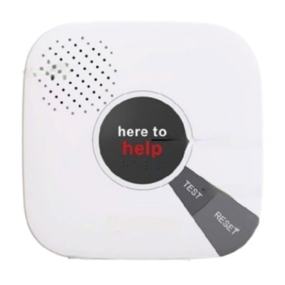
2. Application Overview 1.1. The SUPER 32-DT35A 2.1. Identifying The Parts Medical Alarm TOP VIEW SUPER 32-DT35A is a PSTN medical alarm providing around-the-clock telecare for elderly people. The alarm features long-range RF communications, excellent two-way voice monitoring, multiple reporting protocols and easy programming. -
Page 5: The Power Supply
SUPER 32-DT35A. case of a power failure. During normal operation, the AC power DC Jack adapter is used to supply power to SUPER 32-DT35A and at the same time — DC 12V 1A power adapter recharge battery. takes connection. -
Page 6: How To Install The Control Panel
Important: When drilling into a wall, ensure there are no hidden cables or pipes. 2.5. Programming cable and Local Firmware Update cable Super 32-DT35A has a QT cable A for PC programming and a QT cable B for Local... -
Page 7: Learn-In The Devices
2. Release the Learn Button at the voice Command Learning: prompt “Release the button, Ready to learn sensor.” SUPER 32-DT35A is now in The user can use Commands 93 & 94 to learn devices into the system. learning mode and the white backlight will start flashing quickly. -
Page 8: Remove The Devices
Zone 1 and Zone 2 cannot be removed. If Learn Button is pressed for 6 seconds, Command 81 is used to remove Zone the SUPER 32-DT35A will emit a 5 1 device. countinouus beep to indicate remove Command 82 is used to remove Zone failure. -
Page 9: System Configuration
Failure to enter the correct Access Code A Local Programming Mode Slide Switch is on within 2 minutes will cause SUPER 32- the rear side of SUPER 32-DT35A. The user DT35A to exit the Programming mode can enter local programming mode by sliding automatically. -
Page 10: Dial In Twice (Ring Count Disable)
Follow the protocol below to command SUPER 32-DT35A twice. the SUPER 32-DT35A: Step 1. Dial SUPER 32-DT35A and hang up after first 2 rings, wait for another 8-20 CC # DTMF Function # DTMF sec then call again. - Page 11 When an incoming call matches with any of Telephone Number, and the # the programmed Caller ID(s) (except for symbol at the end to terminate the 11th Caller ID), SUPER 32-DT35A will Function Selection auto-answer the call without checking ...
- Page 12 Number of 4-12 digits. To delete the 1 Tel. number, enter (01) followed by (#), after one short beep, enter another (#). SUPER 32-DT35A will emit another short beep, signaling the 1 Tel. Command 18 number is erased. ...
- Page 13 Dial Call Reporting Table for event number details. Command 20-26 When there is an Alarm or Status Reporting Method event, SUPER 32-DT35A will call the CMS at the designated number for the Commands (20-26) are used to program event. Alarm/Status reporting will be the Alarm reporting method for each Tel.
- Page 14 If the Call Recipient needs more talk time, To terminate the incoming call: (1) press s/he can press any keys except 9 on their the reset button on SUPER 32-DT35A; or, phone set to add another 1-30 minutes press DTMF...
- Page 15 Factory Default is set as (0), OFF. <NOTE> (Silent) If the RESET BUTTON is not pressed within 15 minutes, SUPER 32-DT35A will send one more Help Call report to (Normal) summon help and inform the Monitoring Center that no help has arrived within the past 15 minutes.
- Page 16 To set a new Access code; enter the Upon the correct Access Code received, desired (4-digit number) in Function SUPER 32-DT35A will then open a Full- Selection. Duplex Communication to allow the Call Recipient to speak to SUPER 32-DT35A directly.
- Page 17 When (0) is selected, no code is sent to Function Selection Result Monitoring Centers. When SUPER 32-DT35A is in idle mode, pressing and holding the learn button for 16 seconds (until you hear a long beep) will suspend the Mobility Timer. Pressing (1) - (7)
- Page 18 It is used to select the Follow-On Choice mode or Dial Call Reporting). It can be set for SUPER 32-DT35A after it has made a from (01) (1 minute) - (30) (30 minutes). report to the Monitoring Center. ...
- Page 19 Result Supervision Selection This option is used to enable system supervision function. Once enabled, (000) 0 °C SUPER 32-DT35A will be able to receive (001)-(999) 0.1-99.9 °C the check-in signals from Wrist Pendants (WTR-) indicate their proper Factory Default is set as (350), 35.0°C.
- Page 20 Trigger) command #61, #62 and/or #63. Example of available Key-in options: When multiple Tel. numbers are selected, the SUPER 32-DT35A will always dial in Function Selection respective programmed order. Tel. Number Sequence The latest Command (61-63) setting(s)
- Page 21 If this phone If an emergency alarm is triggered by call fails, SUPER 32-DT35A will not try pressing the Active Button on Fall again. Sensor, the guard time delay time is determined by Command 42, instead...
- Page 22 (0) Enable, SUPER 32-DT35A will send a sec, SUPER 32-DT35A will emit a Pendant Learnt-in report long beep automatically Monitoring Center when no pendent is returns to Programming mode. learnt into the Panel 30 mins after powering Step 3: SUPER 32-DT35A will emit 2 up.
- Page 23 0-9=00-09, A=10, B=11, C=12, returns to Programming mode. D=13, E=14, F=15 Step 3: SUPER 32-DT35A will emit 2 Example: beeps to indicate the device is learnt-in successfully. Device Type 93 + Device ID F1E711A001 should be input as ...
-
Page 24: Pc Programming Mode (Super Tool)
Super 32-DT35A Installing The USB Driver Super 32-DT35A can be programmed via USB port connection of a computer using the Super Tool programming software. If the computer cannot recognize the USB connection, please try installing the USB driver as instructed below. - Page 25 USB port. To download Super Tool programming software, open your browser and type below URL in the address bar: https://www.climax.com.tw/climax-download-super32-dt35a.html. Step 1. Super Tool is a portable application and requires no installation. Simply unzip the file to a desired folder and double-click “SuperTool.exe”...
- Page 26 Step 3. Select the COM port generated for the panel after installing the USB Driver (the USB port connected to the panel), enter Panel Access Code (Default: 8744), and then click “Open”. Step 4. A “Read All command success!” message will pop up. The current firmware version of the panel will be displayed on the top-left corner of the screen.
-
Page 27: Function Tabs
To exit PC programming mode, click “Close” on the top-right corner. 5.4.1. Function Tabs To program Super 32-DT35A, click on different function tabs to see and edit the panel functions. 5.4.1.1 Report The “Report” tab allows the user to configure report settings. - Page 28 Others Other reporting methods include Contact ID, Scancom, Tunstall, Speech, VRI Monitoring protocol, Franklin 4 + 2, Auto CID/ Franklin 4 + 2. When "Others" radio button is selected, the other reporting options will be displayed in the 21#-26# Reporting Method drop-down lists. You can program the Alarm reporting method for each Tel. Number (1st-6th Tel.) by selecting from each drop-down menu respectively.
- Page 29 5.4.1.2 Dial Call Reporting Telephone The “Dial Call Reporting Telephone” tab allows the user to assign a unique telephone number to each event for dial call reporting. This tab is only available when Dial Call Reporting Method is selected. Click on each subtab below to proceed. After editing and updating, click “Write” to apply new settings.
- Page 30 13 No Pendant Learnt-in - When the Panel has no pendant learned-in. 14 Smoke Detector Low Battery - When the Smoke Detector (SD) is under Low Battery status. 15 Smoke Detector Low Battery Restore - When the Smoke Detector (SD) battery is back to normal.
- Page 31 44 Medication Dispenser AC Fail - When AC Power for the Medication Dispenser fails and lasts for 24 hours. 45 Panel Test Button - When the Panel Test Button is pressed to make a test call to CMS. 5.4.1.3. Telephone The “Telephone”...
- Page 32 5.4.1.4. Settings The Settings tab allows you to program general configuration for the panel. Click “Write” when you have completed all settings to confirm. 31# Ringer Enable for Incoming Calls: - When disabled, the panel will operate silent for an in-coming call. - When enabled, the panel will sound a ring tone as an audio alert for an in-coming call.
- Page 33 37# AC Fault Report: - When set to ON, the Panel will send a Fault Report after a continuous one hour of AC Fault condition is detected. - When set to OFF, the Panel will not send an AC fault report. 38# Follow-On &...
- Page 34 44# Mobility Timer: - This function monitors user movement around the premises and sends an inactivity report to the Monitoring Center if the user fails to reset the inactivity timer. - Inactivity Timer can be selected as 12HR, 24HR count down periods, or it can be disabled. - The Mobility Timer counting down can be reset by either pressing the RESET button on the Panel, or movement detected by PIR Detector.
- Page 35 - The Guard Time for Fall Sensor’s fall detection function is set separately from regular Guard Time. - The Panel can be programmed to delay alarm reporting (triggered by Fall detection) from (00) (instant reporting) to (99) seconds. - During Guard Time period, a continuous series of beeps will be emitted to alert user. If a false alarm is triggered by Fall Sensor, it can be cancelled within the Guard Time Delay.
- Page 36 - Set the Low Temperature Reporting threshold in degrees Fahrenheit. (32°F ~ 212 °F) 5.4.1.6 CO2 The CO2 tab allows user to program the CO2 Alarm Reporting threshold. When CO2 concentration value reaches or exceeds the Alarm Reporting threshold, Super 32-DT35A will report CO2 Alarm to CMS. 57# CO2 concentration: - Set the CO2 Alarm Reporting threshold.
- Page 37 5.4.1.7. Device The Device tab allows user to learn in or remove devices from the Panel. 93# Learn-In Silent Device: This is used for learning in silent devices. When the Panel receives the alarm signal from a Silent Device, it will not sound any warning beeps during Reporting and Guard time period. 94# Learn-In Device: This is used for learning in non-silent devices.
- Page 38 Step 2: Press the Device Button within 20 secs, a “Learn Device success!” message will pop up to indicate successful learning. <NOTE> Learning can only be completed within the signal reception range of the Panel. If no signal is received within 20 sec, a “Learning Fail” message will pop up, and the Panel will automatically return to Programming mode.
- Page 39 80# Remove All Device Click “Remove” to remove all devices from the Panel. A message “Remove All Device command success!” will pop up. 81# Remove Zone 1 Device Click “Remove” to remove zone 1 device from the Panel. A message “Remove Zone 1 Device command success!”...
- Page 40 5.4.1.8. Caller ID The Caller ID tab allows the user to program Caller IDs. Click the subtab down below to proceed. Caller ID 201-210, 212-220: - When an incoming call matches with any of the programmed Caller ID(s) (except for the Caller ID 211), the Panel will auto-answer the call without checking access code or any button press.
-
Page 41: Profile
5.4.2. Profile The Profile function allows you to create and edit different setting profiles which can be easily accessed in the future for quick programming. Current Setting After reading the configuration of the Panel, the Profile scroll down bar will now display “Current Setting”... - Page 42 Delete Profile Select a profile and click on “Delete Profile”. A pop-up window will ask you to confirm the selection: Select “Yes” to delete the profile, or “No” to return to the previous page. Profile Backup & Transfer The profiles that you created and saved are stored as text files in the “Profile” folder under the directory where the Super Tool files are extracted in your local computer.
-
Page 44: Operation
When the battery low condition lasts for 4 By default 15-minute is allowed for each call. - 6 mins, SUPER 32-DT35A will report to the Monitoring Center, and the GREEN LED slowly flashes. 6.1.2. Auto-Answer Incoming Calls ... -
Page 45: Devices Low Battery
GREEN LED flashes slowly. When the Mobility timer is not reset after 30 minutes, SUPER 32-DT35A will send a After the battery is restored for 10-15min, Mobility Timer Expired report to the SUPER 32-DT35A will send Battery Monitoring Center. -
Page 46: Alarm Activation
During the Guard Time period, and “Fall detection has restored, pressing the RESET button on cancelling help call” voice prompt, SUPER 32-DT35A, it will cancel the when fall detection been alarm signal and return to Idle Mode. cancelled during guard time. - Page 47 Follow On Operation COMMUNICATION Enter (1) to TALK ONLY During the Follow-On period, the Monitoring Center can remotely control SUPER 32-DT35A Enter (3) to LISTEN-IN ONLY by the DTMF commands below: Enter (9) to HANG UP 1.
- Page 48 Tel. #6. It is recommended to set digital reporting method in first priority Pressing the RESET button, the for immediate help. SUPER 32-DT35A will report to the Monitoring Center that help has If either Digital Alarm reporting OR arrived.
-
Page 49: Walk Test (Range Test)
If Dial Call Reporting Method is selected, of its operation. SUPER 32-DT35A will call the CMS at the Step 4. If SUPER 32-DT35A responds with designated number for the alarm event. one long beep, then the particular Voice Prompt “Calling the Care Center”... -
Page 50: Global Test
#00) used button. Enable/Disable system reporting function. Step 3. SUPER 32-DT35A will emit a short beep, voice prompt “Global When SUPER 32-DT35A is in normal Test”, and report to Monitoring operation with reporting function enabled, Center. calling the SUPER 32-DT35A with the 11 Caller ID will disable the system reporting function. -
Page 51: Appendix
When the HELP Panel button is 302 - Panel Low battery pressed. When SUPER 32-DT35A is under Low 101 - Personal emergency Battery status, the Green LED flashes every 2 secs with 2 beeps every hour. -
Page 52: Tunstall Event Code
30 secs. D#1019 - Panel Low battery When SUPER 32-DT35A is under Low 7.2. Tunstall Event code Battery status, the Green LED flashes every 2 secs with 2 beeps every hour. -
Page 53: Vri Event Code
555556558 - Panel Low battery When Smoke Detector (SD) button is pressed. When SUPER 32-DT35A is under Low Battery status, the Green LED flashes 355555557 - SD or CO emergency every 2 sec with 2 short beeps every restore hour. - Page 54 – Panel Battery Fall emergency When SUPER 32-DT35A is under Low Battery status, the Green LED flashes every 2 secs with 2 beeps every hour. When Fall Sensor is triggered. 77 – Low Battery Restore(For PIR/ SD/ CO/ WS) ...
-
Page 55: Dial Call Reporting Table
7.5. Dial Call Reporting Table Event Number Event Condition Default Dial Number Panel emergency When the HELP Panel button is pressed. Pendant 1 emergency When Pendant 1 is pressed or triggered. Pendant 2 emergency When Pendant 2 is pressed or triggered. Pendant emergency When Pendant 1 is pressed or triggered... - Page 56 Battery Dead When the battery is restored for 10- 15min. Battery Dead Restore When SUPER 32-DT35A is unable to receive the signal transmitted from the WTR Supervision Failure Wrist Transmitter / Emergency Pendant (WTR) for a pre-set period by Command...
- Page 57 Event Number Event Condition Default Dial Number When the Fall Sensor battery is back to Fall Sensor Low Battery normal. Restore When the IR Sensor is in low battery IR Sensor Low Battery status. IR Sensor Low Battery When the IR Sensor battery is back to Restore normal.
-
Page 58: Super 32-Dt35A Programming Command Table
7.6 SUPER 32-DT35A Programming Command Table DTMF DTMF TERMI- DTMF COMMAND OPERATION DEFAULT CHARACTER NATOR COMMANDS To Set Telephone Dialing Report Number (001-200) Enter: Dialing Number Sequence + * + Event Number + Telephone Number Note: Dialing Number Sequence: 001-200 Symbol: * Event Number: 00-19 (See 6.5. - Page 59 DTMF TERMI- DTMF DTMF COMMAND OPERATION DEFAULT CHARACTER NATOR COMMANDS To Set Reporting Method for Tel. Number 1 0 = Contact ID , 1 = Scancom, 2 = Tunstall 3 = Speech, 4=VRI, 6 = Franklin 4 + 2, 8 = Auto CID/Franklin 4-2, 9 = Dial Call Reporting (Note: When any of the command 20-26 is set to 9 Dial Call Reporting...
- Page 60 DTMF TERMI- DTMF DTMF COMMAND OPERATION DEFAULT CHARACTER NATOR COMMANDS Silent Mode Silent mode Off 0 = Silent mode On, 1 = Silent mode Off AC fault report, 0 = Off, 1 = On Follow-On & Call Back Function, 0 = Follow-On, 1= Follow-On Call-Back, 2= Follow-On &...
- Page 61 DTMF TERMI- DTMF DTMF COMMAND OPERATION DEFAULT CHARACTER NATOR COMMANDS Remove Zone Two Device Learn-in silent devices Bi Bi No devices Learn-in non-silent devices (smoke detectors, CO detectors, pendants and fixed emergency Bi Bi No devices transmitters, long range pendants) Learn-in sensor with device ID: Enter Device Type (93 or 94) + Device ID Input rule:...
-
Page 62: Super 32-Dt35A Voice Prompts
7.7. SUPER 32-DT35A Voice Prompts The Control Panel plays voice prompts on important occasions to report its condition or remind you to take a specific action. Information on voice prompts is provided in the chart below. Voice Prompt Condition Played once after long pressing (6 seconds) the Learn Button on the Release the Button Control Panel to enter learning mode.
Need help?
Do you have a question about the SUPER 32-DT35A and is the answer not in the manual?
Questions and answers