Table of Contents
Advertisement
Quick Links
Advertisement
Table of Contents

Related Manuals for Watts R4X40


Summary of Contents for Watts R4X40
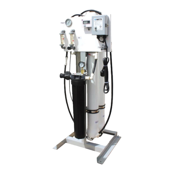
- Page 1 REVERSE OSMOSIS INSTALLATION AND OPERATION MANUAL Model R4X40...
- Page 3 IMPORTANT Please read the entire manual before proceeding with the installation and startup: Do not use where the water is microbiologically unsafe. Always turn off the unit, shut off the feed water, and disconnect the electrical power when working on the unit.
-
Page 4: Table Of Contents
TABLE OF CONTENTS I. Introduction Specifications RO Overview Pre-treatment II. Controls, Indicators, and Components III. Operation Installation Plumbing Connections Electrical Startup Control Function Operation and Maintenance Log Troubleshooting IV. Replacement Parts List V. Membrane Replacement VI. Appendix Temperature Correction Factors... -
Page 5: Introduction
The concentration of each dissolved ionic species must not exceed the limits of solubility anywhere in the system. Pre-treatment must be sufficient to eliminate chemicals that would attack the membrane materials. A. SPECIFICATIONS R4X40-1 R4X40-2 R4X40-3 Maximum Productivity (gallons per day) 2200... -
Page 6: Overview
B. RO OVERVIEW Reverse osmosis systems utilize semipermeable membrane elements to separate the feed water into two streams. The pressurized feed water is separated into purified (product) water and concentrate (reject) water. The impurities contained in the feed water are carried to drain by the reject water. -
Page 7: Controls, Indicators, And Components
Prefilter Cartridge - Used to remove smaller suspended solids and trap any particles that may be generated by the other pretreatment. The cartridge(s) should be replaced when the pressure drop across the housing increases 5 - 10 psig over the clean cartridge pressure drop. The effect of suspended solids is measured by the silt density index (SDI) test. - Page 8 Figure 1...
- Page 9 Controller Connections Figure 2...
-
Page 10: Operation
Make sure the on / off switch in the off position (Figure # 1 item A). Plug the unit into a 115 volt 3 prong outlet. Note – The R4X40-2 requires a 20 amp outlet. Systems configured for 230 volts do not come with a plug. -
Page 11: Startup
D. STARTUP 1. Verify that the pretreatment equipment is installed and working properly. Verify that no free chlorine is present in the feed water. 2. Verify that the on / off switch is in the off position. 3. Verify that a filter cartridge is installed in the prefilter housing. 4. - Page 12 product water TDS. The meter will automatically turn it self off after a few seconds. The quality meter is powered by two AAA batteries. To replace the batteries, lift the meter out of the bracket and remove the back cover.
-
Page 13: Operation And Maintenance Log
Operation and Maintenance Log DATE PRODUCT REJECT PUMP FEED PRODUCT FEED FEED FEED WATER PRE FILTER PRE FILTER REMARKS DISCHARGE WATER WATER CHLORINE INLET OUTLET PRESSURE TEMP HARDNESS LEVEL PRESSURE PRESSURE Note: Change the prefilter when the differential pressure increases by 5 - 10 psi over the clean differential pressure. Clean the RO membrane(s) when the product flow drops by 15% or more. -
Page 14: Troubleshooting
G. TROUBLESHOOTING RO MEMBRANE TROUBLE SHOOTING GUIDE SYMPTOMS Salt Passage Permeate Flow Pressure Drop Location Possible Causes Verification Corrective Action Normal to Decreased Normal to Predominantly Metal oxide Analysis of metal Improved pretreatment increased increased first stage ions in cleaning to remove metals. -
Page 15: Replacement Parts List
R4507 Reject flow meter with valve 0.5 – 5 gpm R5316 WDM-2 Water quality meter R6316-HPS7D Pump & motor 0.75 HP for R4X40-1 R6316-HPS7E Pump & motor 1.0 HP for R4X40-2 R6316-HPS10F Pump & motor 1.5 HP for R4X40-3 R23-1075 Controller with on/off switch Low pressure switch, ¼”... -
Page 16: Membrane Replacement
MEMBRANE REPLACEMENT 1. Turn off the system and close the feed water shutoff valve. 2. Unplug the unit. 3. Disconnect the tubing from the top of the membrane housing(s). 4. Loosen the clamps and remove the top end cap(s). 5. Remove the old membrane(s) by pulling them up and out of the housings. You may need to grab the old membrane with a pair of pliers. -
Page 17: Appendix
VI. APPENDIX The following tables are intended as a guide to determining the flow rates for the R4X40 series RO systems. All flows are in gallons per minute (GPM) with 77°F feed water. Nominal flows for systems operating at 50% recovery with a feed water SDI < 1. -
Page 18: Temperature Correction Factors
Temperature Correction Factors Deg C Deg F Correction Factor 1.00 75.2 0.97 73.4 0.94 71.6 0.92 69.8 0.89 0.86 66.2 0.84 64.4 0.81 62.6 0.79 60.8 0.77 0.74 57.2 0.72 55.4 0.70 53.6 0.68 51.8 0.66 0.64 48.2 0.62 46.4 0.61 44.6 0.59...
Need help?
Do you have a question about the R4X40 and is the answer not in the manual?
Questions and answers