Table of Contents
Advertisement
Advertisement
Table of Contents

Related Manuals for Watts R12-Wall Mount


Summary of Contents for Watts R12-Wall Mount
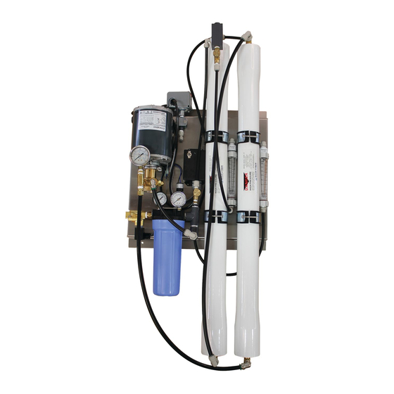
- Page 1 REVERSE OSMOSIS INSTALLATION AND OPERATION MANUAL R12-Wall Mount...
- Page 3 Never allow the unit to freeze or operate with a feed water temperature above 100°F. NOTES Changes in operating variables are beyond the control of Watts. The end user is responsible for the safe operation of this equipment. The suitability of the product water for any specific application is the responsibility of the end user.
-
Page 4: Table Of Contents
TABLE OF CONTENTS I. Introduction Specifications RO Overview Pre-treatment II. Controls, Indicators, and Components III. Operation Installation Plumbing Connections Electrical Startup Control Function Operation and Maintenance Log Troubleshooting IV. Replacement Parts List V. Membrane Replacement VI. Appendix Temperature Correction Factors... -
Page 5: Introduction
INTRODUCTION The separation of dissolved solids and water using RO membranes is a pressure driven temperature dependent process. The membrane material is designed to be as permeable to water as possible, while maintaining the ability to reject dissolved solids. The main system design parameters require the following: Internal flows across the membrane surface must be high enough to prevent settling of fine suspended solids on the membrane surface. -
Page 6: Ro Overview
B. RO OVERVIEW Reverse osmosis systems utilize semipermeable membrane elements to separate the feed water into two streams. The pressurized feed water is separated into purified (product) water and concentrate (reject) water. The impurities contained in the feed water are carried to drain by the reject water. -
Page 7: Controls, Indicators, And Components
Prefilter Cartridge - Used to remove smaller suspended solids and trap any particles that may be generated by the other pretreatment. The cartridge(s) should be replaced when the pressure drop across the housing increases 5 - 10 psig over the clean cartridge pressure drop. The effect of suspended solids is measured by the silt density index (SDI) test. - Page 8 Figure 1...
-
Page 9: Operation
III. OPERATION A. INSTALLATION Proper pretreatment must be determined and installed prior to the RO system. The water supply and pretreatment equipment should be sufficient to provide a minimum of 10-psig at the maximum feed flow. An electrical receptacle with a ground fault interrupt (GFI) is highly recommended. Responsibility for meeting local electrical and plumbing codes lies with the owner / operator. -
Page 10: Startup
D. STARTUP 1. Verify that the pretreatment equipment is installed and working properly. Verify that no free chlorine is present in the feed water. 2. Verify that the on / off switch is in the off position. 3. Install a 10" five micron filter cartridge in the prefilter housing. 4. -
Page 11: Operation And Maintenance Log
Operation and Maintenance Log DATE PRODUCT REJECT PUMP FEED PRODUCT FEED FEED FEED WATER PRE FILTER PRE FILTER REMARKS DISCHARGE WATER WATER CHLORINE INLET OUTLET PRESSURE TEMP HARDNESS LEVEL PRESSURE PRESSURE Note: Change the prefilter when the differential pressure increases by 5 - 10 psi over the clean differential pressure. Clean the RO membrane(s) when the product flow drops by 15% or more. -
Page 12: Troubleshooting
G. TROUBLESHOOTING RO MEMBRANE TROUBLE SHOOTING GUIDE SYMPTOMS Salt Passage Permeate Flow Pressure Drop Location Possible Causes Verification Corrective Action Normal to Decreased Normal to Predominantly Metal oxide Analysis of metal Improved pretreatment increased increased first stage ions in cleaning to remove metals. -
Page 13: Replacement Parts List
RO SYSTEM TROUBLE SHOOTING PROBLEM REMEDY General High Product Water TDS Membrane frozen, high temp, or backpressure. Replace membrane. Membrane attack by chlorine Carbon pre-filter may be exhausted. Replace filter and membrane. Product seal on end cap. Determine if seal or o-ring is bad. Replace as needed. No Product Water or Not Enough Product Water Feed water shut off. -
Page 14: Membrane Replacement
MEMBRANE REPLACEMENT 1. Turn off the system and close the feed water shutoff valve. 2. Disconnect the tubing from the pressure vessel. 3. Remove the retaining "U" pins from the pressure vessels. 4. Push the old membrane out of the vessel in the direction of the feed flow 5. -
Page 15: Appendix
VI. APPENDIX The following tables are intended as a guide to determining the flow rates for the R12 series RO systems. All flows are in gallons per minute (GPM). Nominal flows for systems operating at 50% recovery. R12-0150 R12-0250 R12-0600 R12-1200 Product 0.10...
Need help?
Do you have a question about the R12-Wall Mount and is the answer not in the manual?
Questions and answers