Advertisement
Quick Links
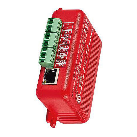
HW-AV-LTE-M
CLSS Pathway
Product Installation Document
1 Overview
The CLSS Pathway (HW-AV-LTE-M) is a dual-path cellular communicator. It transmits data from a fire alarm control panel (FACP)
to a central monitoring station. It communicates over AT&T and Verizon networks. The SIM cards are configured in an active/active
state, and will automatically fail over from Verizon to AT&T in the event of a cellular outage. It transmits Contact ID, SIA, or 4x2 data
from the fire alarm control panel to the supervising station or monitoring center (Supported SIA formats- SIA8, SIA20, SIA2000.
Supported 4x2 frequencies - 1400 Hz, 2300 Hz).
This document includes instructions for mounting and wiring only. For this purpose, the guide uses the optional enclosure
HW-AV-ENC.
1.1 Other Features
This communicator also has other features, including secondary datra transmission via an Ethernet connection as well as
monitoring dry-contact relay outputs.
1.2 Information Sources
• For more detailed procedures and all configuration options refer to the Installation and Operation Manual (LS10340-
000HW-E)
• For quick install and to configuration the CLSS Pathway refer to the Quick Start Guide (LS10339-000HW-E), which comes
with the communicator.
• To access the most updated versions of all product documentation, log on to CLSS Site Manager and access the help
section.
2 Mounting the Communicator
CAUTION: REQUIRED ENCLOSURE
!
THE CLSS PATHWAY SHALL ONLY BE MOUNTED WITHIN A HW-AV-ENC ENCLOSURE.
Notes
• Inform the central monitoring station to put your Account on test.
• If installing on an existing operational panel, inform the operator and the local authority that the panel will be temporarily out
of service.
• Check that you have the communicator, 3-ft antenna, and the Quick Start Guide from the carton box.
• Only a regulated UL-listed UOJZ, UTOU, or NBSX control panel or power supply should power the communicator.
• The communicator must be connected to a UL-listed control panel with power limited circuits.
• For UL installations, secure the communicator to a UL-listed enclosure, such as a UL-listed junction box or HW-AV-ENC.
• Install the communicator only at a dry indoor location.
• The location and wiring methods must be in accordance with the National Electrical code, ANSI/NFPA 70.
• Install in accordance with the National Fire Alarm and Signaling Code, NFPA 72.
• Mount the communicator inside an enclosure, for example HW-AV-ENC, as shown in
• Enclosure should be close nipple to the fire alarm control panel.
2.1 Before Mounting
1.
Know whether to install CLSS Pathway for dialer capture or for panel relay monitoring.
2.
If it is for dialer capture, know whether to install the CLSS Pathway with LAN (dual-path communications) or without LAN
(sole path).
3.
The panel should be programmed to support the CLSS Pathway.
4.
Before mounting and wiring, ensure that the panel is powered down.
2.2 To Mount the Communicator
1.
In the Quick Start Guide (included with the product), locate the installation sticker at the bottom right of the last page.
2.
Check that the sticker has the serial number and the configuration key to program the communicator.
3.
Place the sticker on the inside lid of the enclosure for programming steps and for future reference.
4.
Mount the enclosure box on the wall next to the fire panel using the wall mounting holes.
Document: LS10338-000HW-E:B
09/13/2024
ECN: 54592
Figure 1
below.
Advertisement

Related Manuals for Honeywell CLSS Pathway


Summary of Contents for Honeywell CLSS Pathway
- Page 1 2.1 Before Mounting Know whether to install CLSS Pathway for dialer capture or for panel relay monitoring. If it is for dialer capture, know whether to install the CLSS Pathway with LAN (dual-path communications) or without LAN (sole path). The panel should be programmed to support the CLSS Pathway.
-
Page 2: To Connect The Antenna
• Supported frequency must either be between 700/850 or 1700/1900 MHz. • Connector: SMA Connector, SMT 13.5 mm, 50 ohms. • The maximum length of cable should not exceed 20 feet. CLSS Pathway Product Installation Document — P/N LS10338-000HW-E:B 09/13/2024... - Page 3 4.1 Wiring for Dialer Capture For dialer capture, you connect both telephone ports of the fire panel with the communicator. If a dual-path connection is needed, connect the LAN port of the CLSS Pathway with the customer’s network router. 4.1.1 Preparations •...
- Page 4 Ensure that the Green LED on the communicator is continuously ON indicating successful connections. NOTE: Refer to Section 7, “Troubleshooting” if there is an issue to resolve. 4.3 For Dual-path Communications Connect the LAN port of the communicator to the customer’s network. CLSS Pathway Product Installation Document — P/N LS10338-000HW-E:B 09/13/2024...
-
Page 5: Troubleshooting
• The communicator device is damaged. Replace with an undamaged communicator. • Trying to establish connection. Reposition the antenna. Flashing Slow • No cellular signal available. Low signal connectivity Reposition the antenna. Flashing every 5 seconds CLSS Pathway Product Installation Document — P/N LS10338-000HW-E:B 09/13/2024... - Page 6 2. Ensure that the signal strength shown on it is at least one to two bars. 3. Reposition the antenna for higher signal strength. Honeywell International Inc. 12 Clintonville Rd. Northford, CT 06472 LS10338-000HW-E | B | 09/24 800.627.3473 ©2024 Honeywell International Inc. Technical support: CLSS. T ech@Honeywell.com...
Need help?
Do you have a question about the CLSS Pathway and is the answer not in the manual?
Questions and answers