Table of Contents
Advertisement
Quick Links
Advertisement
Table of Contents

Related Manuals for Cold Jet i3 MICROCLEAN 2


Summary of Contents for Cold Jet i3 MICROCLEAN 2
- Page 1 Original Instructions [English] 11/2020 Rev New...
- Page 2 Cold Jet and the client and remains the exclusive property of Cold Jet. If you find any problems in the documentation, please report them to us in writing. Cold Jet does not warrant that this document is error-free.
-
Page 3: Table Of Contents
Contents Introduction ................................1 Safety ..................................3 MicroClean 2 System Description ......................7 Operations ................................15 Cold Jet CONNECT™ ............................36 Maintenance ..............................43 Warranty ................................45 Technical Schematics............................47 Contact Information ............................58... - Page 5 AC VOLTS __________________________________________________________________________________________________________________ PHASE ______________________________________________________________________________________________________________________ FREQUENCY _______________________________________________________________________________________________________________ AMPS _______________________________________________________________________________________________________________________ MAX OPERATION PRESSURE _____________________________________________________________________________________________ MOTOR KW ________________________________________________________________________________________________________________ Mo./Yr. _____________________________________________________________________________________________________________________ SCCR ________________________________________________________________________________________________________________________ Supplier Responsible for the Equipment: Cold Jet, LLC 455 Wards Corner Road Loveland, Ohio 45140 USA Phone: +1-800-777-9101 Website: www.coldjet.com...
-
Page 7: Introduction
IoT/Industry 4.0 technologies. This machine adds to Cold Jet’s existing “smart” dry ice blasting portfolio with its data monitoring and diagnostic features with Cold Jet CONNECT. It allows customer’s key insights on the machine’s ongoing operation while also providing Cold Jet’s technical support staff the ability to view these operational parameters for... -
Page 9: Safety
Safety General Safety Guidelines This machine is designed to comply with international design standards and the European Machinery Directives. Therefore, using the machine does not pose a risk to the operator when the instructions in this manual are followed carefully. However, certain precautions must be followed during its use. - Page 10 Safety Labels The symbols used on the machine were developed by the International Organization for Standardization (ISO) and are defined below. These symbols may include yellow warnings triangles, blue mandatory action circles, or red prohibited action circles. Symbol Definition General Warning Cold Temperature Warning Pressurized Material Ejection Hazards Electrostatic Discharge Warning...
- Page 11 High pressure hoses, fittings and couplings are important for the safety of the machine. Use only hoses, fittings and couplings recommended by Cold Jet. WARNING To ensure machine safety, use only original spare parts from Cold Jet or approved by Cold Jet. WARNING The applicator and applicator hose contain electrical connections.
- Page 12 WARNING Do not use the machine if a supply cord or important parts of the machine are damaged, e.g. safety devices, high pressure hoses, applicator. WARNING Inadequate extension cords can be dangerous. If an extension cord is used, it shall be suitable for the environment in which it is used, if used outdoors the connection has to be kept dry and off the ground.
-
Page 13: I3 Microclean 2 System Description
MicroClean 2 System Description The standard accessory package is as follows: 1/2 in (12.7 mm) in Precision Applicator 2 Precision nozzles 1/2 in (12.7 mm) Air supply hose 25 ft (7.62 meters) 1/2 in (12.7 mm) all rubber blast hose 12 ft (3.66 meters) - Page 14 ½ in (12.7 mm) Precision Applicator with on/off; air only; light control Control/Display 7 in (17.7 cm) LCD screen with rotary encoder dial Communication IoT connectivity via a cellular 3G/LTE Global and Cold Jet Connect™ Noise level 60 dB(A) up to 130 dB(A) Noise Level The i MicroClean 2 has many features such as Nozzle selection, air pressure settings, and hose size.
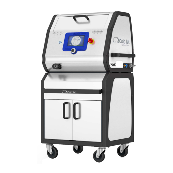
- Page 15 MicroClean 2 Components * Note: The i MicroClean 2 is shipped with a QDC air supply fitting installed. There is a Claw type adapter fitting located inside the drawer if required for air supply connection to the i MicroClean 2.
- Page 16 Precision Applicator Components Nozzle Applicator Lights Applicator Controls Trigger Trigger Safety Blast Hose Connection Applicator Control Cable Precision Applicator Nozzles Nozzle Air Consumption Blast Swath Dry Ice Feed Rate Length Material (MC13) 12 CFM@80 psi 0.13 in 0.1-0.4 lbs/min 6 in Plastic Yellow (0.3 m...
- Page 17 Nozzle Air Consumption Blast Swath Dry Ice Feed Rate Length Material 25 CFM@80 psi 0.88 in 0.2-1 lbs/min 5 in Plastic & (MC88F) (0.7 m /min 5.5 bar) (2.2) cm 0.1-0.5 kg/min (12.7 cm) Aluminum Fragmenting Fan 30 CFM@80 psi 0.88 in 0.5-1.2 lbs/min 5 in...
- Page 18 Control Panel and HMI Screens This i MicroClean 2 uses a rotary encoder dial that allows the operator to navigate, select and adjust settings on the control panel screen. You must first press the rotary encoder to activate navigation. Navigate between options by turning the rotary encoder dial left or right; this will highlight the option in blue.
- Page 19 Figure 2: Home Screen 1. Air Pressure In 2. Feed Rate 3. Blast Pressure Figure 3: Settings Screen 1. Home 2. Recipes 3. Machine Status 4. Advanced Settings 5. Applicator Light 6. Screen Lock...
- Page 20 During operation, some items on the screen will indicate level or failure mode by changing colors. Green is normal, yellow or orange is a warning and red needs immediate attention. Figure 4: Numeric Color Indicator Numbers change state too. White is normal, orange is warning, and red needs immediate attention.
-
Page 21: Operations
Refer to the packing slip for a list of the components shipped with the machine. Contact Cold Jet if any damage has occurred to the shipping container or the machine (see “Contact Information” on page 58). - Page 22 Transport and Storage The following instructions are for proper transport of the i MicroClean 2. Follow all instructions as illustrated to avoid damaging the i MicroClean 2. It is recommended that only trained and qualified personnel use and move the i MicroClean 2.
- Page 23 Ensure that the cabinet locks are secure on each side of the i MicroClean 2 cabinet.
- Page 24 If removing the MicroClean 2 from the cabinet, you must disconnect the lines that are attached to the exhaust ports as shown: Air Line Exhaust Ports To lift using a fork lift, use the method illustrated: Secure the MicroClean 2 before lifting or moving on a fork lift to prevent it from sliding or falling off the skid.
- Page 25 WARNING Do not lift the MicroClean 2 using the lid handle bar, rear cable holder which will cause damage and/or harm to personnel.
- Page 26 Personal Protective Equipment (PPE) WARNING Only trained and or certified personnel should operate the MicroClean 2. WARNING Do not operate the MicroClean 2 without proper PPE. Prior to operating the MicroClean 2, or loading dry ice into the trough, proper PPE must be used. It is recommended that each operator is trained on the proper use of PPE.
- Page 27 Setting Up the i MicroClean 2 WARNING Improper installation of hoses and adapters to the MicroClean 2 can cause damage to the machine or the applicators. Do not use one wrench when tightening or replacing fittings on the MicroClean 2 machine or the applicators.
- Page 28 Always use two wrenches to install and remove hoses and accessories on the MicroClean 2 or the applicators to prevent damaging the internal components. 4. Attach a nozzle to the applicator. 5. Connect the static ground reel to the target surface. 6.
- Page 29 Compressed Air Supply For best results while blasting, incoming air supply must be as free of oil and dirt as possible. It is recommended that the incoming supply air— filters, oil filters, and water separators are continuously monitored to ensure the MicroClean 2 receives the air your machine use is specified for.
- Page 30 3. Load or reload dry ice into the MicroClean 2: a. On the Precision applicator, press the air+ice button (II) to deactivate (green light OFF). This will also deactivate the applicator. b. On the MicroClean 2, open the lid. (Optional DX model shown) Figure 7: Trough Door DX Insert Pins...
- Page 31 c. Open the DX cover by pulling the pins inward if equipped. d. Check the inside for the presence of any foreign material or condensate and clean or remove as necessary. e. Fill to the red line when using pellets for DX model only. Do not use pellets unless the DX panels are installed.
- Page 32 CAUTION Use only Cold Jet approved dry ice for blast media. The use of any other media will lead to loss of warranty coverage h. Close the DX cover if equipped. Close the trough lid. Blasting Dry Ice Particles For optimum performance while blast cleaning: Position the MicroClean 2 and blast hose to prevent kinking and allow for maximum maneuverability.
- Page 33 b. To select a recipe: Use the rotary encoder dial to navigate to the Settings screen then to the Recipe screen. ii. Use rotary encoder dial to select the recipe menu and adjust it to the desired recipe numbered 1-9 (see “Recipes” on page 28). Figure 8: Set Up Screen 1.
- Page 34 b. Pull the trigger to blast for 10 seconds. c. After blasting, press the air button (I) again to deactivate (blue light off). This should also deactivate the applicator. d. Remove nozzle from applicator CAUTION Do not touch nozzle with bare hands during or immediately after use.
- Page 35 4. Turn off the compressed air supply. The MicroClean 2 will automatically bleed any remaining pressure. There is no need to bleed the air pressure from the MicroClean 2. The MicroClean 2 automatically bleeds air pressure during proper shut down of the MicroClean 2.
- Page 36 Screen Lock The following screens describe how to lock the screen so that the blaster settings cannot be changed. 1. Home 2. Recipes 3. Machine Status 4. Advanced Settings 5. Applicator Light 6. Screen Lock a. From the settings screen, select “6” using the rotary encoder dial to access the screen lock screen.
- Page 37 b. Using the rotary encoder dial, select the top blank line of the password entry screen and press the dial once. c. Select a number and press the dial again to enter the selected number. d. Repeat until three numbers have been populated. e.
- Page 38 Recipes The following screens describe the recipe functions for the MicroClean 2. Recipes are useful for saving optimal settings for the machine for different types of surfaces. This saves time when switching from one type of surface to another. Below describes how to save recipes and how to recall for use.
- Page 39 Emergency Stop The emergency stop button is used in the event that the MicroClean 2 must be shut down immediately. If any event occurs that could cause harm to personnel or equipment then use the emergency stop to shut down the MicroClean 2. The Emergency stop button is a push pull button. Once pushed, the button must be rotated clockwise to reset.
- Page 40 Reset Screen The reset screen appears if the emergency stop has been activated or the lid to the trough has been opened. When the reset screen appears, first correct the issue. If the emergency stop has been activated — reset the emergency stop by rotating clockwise. If the lid has been opened or is opened, close it.
- Page 41 Cold Jet ConnectTM platform where you can view the machine’s operating conditions. In addition, through the machine’s control panel you can initiate Diagnostic Mode when working with Cold Jet’s technical service personnel which will send a sustained burst of more detailed operating data for help in evaluating technical issues.
-
Page 42: Cold Jet Connect
In the increasingly smart connected world, technology makes it easier to support and maintain your Cold Jet equipment. As part of our commitment to the support of your dry ice blasting machine, it comes with its own personal support site through MyColdjet.com and a link to Cold Jet CONNECT –... - Page 43 Click the menu icon in the upper left-hand corner to access on-line manual (s), warranty information, technical service contacts, service parts ordering, and a link to this machine’s Cold Jet CONNECT operational view.
- Page 44 “Authentication” code, you can request it by clicking the “click here” link located at the bottom of the page. For more information regarding Cold Jet CONNECT, access the user guide by clicking the help icon in the top right-hand of the screen.
- Page 47 EU Declaration of Conformity Original EN This declaration is issued under the sole responsibility of the Cold Jet group: Cold Jet, LLC 455 Wards Corner Road Loveland, Ohio 45140 USA Hereby declare the following product: Product Designation: MicroClean Type/Serial Number:...
-
Page 49: Maintenance
MicroClean 2 to prevent damage to the system or a error serious in nature has occurred in which case you will need to contact Cold Jet Customer Service. The MicroClean 2, in error shut down mode, will continue powered up but will not operate. -
Page 51: Warranty
Warranty Cold Jet® (“CJ”) warrants its products (“Equipment”) provided under this Agreement to be free from defects in materials and workmanship for a period of 12 months (90 days on used equipment), under normal use, maintenance and service as stipulated in the Operator’s Manual, Commissioning, and Operator Training. At the discretion of CJ, failure to complete Installation, Commissioning, and Operator Training shall result in forfeit of warranty rights. -
Page 53: Technical Schematics
Technical Schematics Assembly Drawing with Pneumatic Schematics [2A0338] ..............47 Electrical Schematics [6G0536] ......................... 49... - Page 63 NOTES: _________________________________________________________ _________________________________________________________ _________________________________________________________ _________________________________________________________ _________________________________________________________ _________________________________________________________ _________________________________________________________ _________________________________________________________ _________________________________________________________ _________________________________________________________ _________________________________________________________ _________________________________________________________ _________________________________________________________ _________________________________________________________ _________________________________________________________ _________________________________________________________ _________________________________________________________ _________________________________________________________ _________________________________________________________ _________________________________________________________ _________________________________________________________ _________________________________________________________...
-
Page 64: Contact Information
1727 Industrial Road, Unit 1 After Hours Support: +1-800-777-9101 Cambridge, Ontario N3H 5G7 Email: service@coldjet.com Latin America - Cold Jet Latinoamérica Phone: +52 (81) 1097-0445 San Alberto 404 P2 Col. Residencial After Hours Support: +1 (513) 576-8981 Santa Barbara Email: soporte@coldjet.com...
Need help?
Do you have a question about the i3 MICROCLEAN 2 and is the answer not in the manual?
Questions and answers